Avionics
The Avionics-Subsystem includes all electrical components of the rocket. It controls all functions of the rocket, logs sensor data and communicates with the ground equipment.
The subsystem is constructed in a modular way and all safety-critical components are redundant wherever possible (and partially usable independently of the rest of the system). For high flexibility and low wiring complexity the modules communicate via two redundant communication busses and are supplied by two redundant supply busses. The integration of new modules and the removal of no longer needed ones is thus easily possible.
The tasks of the avionics include controlling the flight sequence, controlling the engine, controlling the flight path, activation of the recovery system and monitoring all sensor data to automatically abort the flight in a safe way in case of certain problems.
The avionics communicate with the ground systems via radio (and prior to lift off also via a wired connection) to control the pre-flight sequence (fuelling, system checks), to monitor sensor data and to abort the flight manually. The radio connection to multiple ground stations is also used for tracking the position of the rocket.
Subscale Test Stand
In order to supplement and verify the calculations and trade studies done to find an appropriate injector concept, a small-scale test engine was built. It is based on a preexisting design built in 2018 but is a lot more modular in order to easily test different injector types and configurations.
In addition, this small-scale engine provides an opportunity for our team to practice the operation of a rocket engine under more forgiving conditions than would be the case with a full-scale engine.
The engine is configured to use ethanol as fuel and oxygen enriched air (NitrOx) as oxidizer at an oxidizer to fuel ratio of 2.5. It is expected to reach a specific impulse of close to 200 seconds and was designed to deliver 200 newtons of thrust. The oxidizer system has a working pressure of 20 bar, the fuel system of 30 bar and the engine itself runs at a chamber pressure of 10 bar. For the first round of cold flow tests, to check the functionality of the setup itself, water will be used as a substitute for the fuel and nitrogen in place of the oxidizer.
Scope of the tests
The primary focus of this test setup is to find the optimal injector configuration. The configurations which will be tested include:
- Showerhead injectors with varying number, position, and cross section of openings.
- Doublet impinging injectors with varying number, position, cross section, and angle of openings.
- Pintle injectors with varying cross sections.
- Swirl injectors with varying cross section and angle of the fuel openings.
- Secondarily this setup will also give us data on the feasibility of using critical venturis for mass flow regulation.
To operate the test stand a computer operator and one person at each pressure regulator are needed. In addition, the presence of a safety manager and a dedicated sensors operator are useful.
After the assembly of the test setup the computer operator does an electronics check. This includes opening and closing the electronic valves and activating the ignition. If everything is nominal the sensors operator switches on the camera filming the test, then the whole test crew evacuates the test stand and assumes their positions on the control stand. The fuel and oxidizer operators pressurize the system, then the computer operator starts the pre programmed test sequence. In case of irregularities during the test it is either interrupted via the control software or, if the issue is with the electronics, the fuel and oxidizer operators open the manual safety valves cutting off the pressure from the system and depressurizing the lines and the fuel tank. After a successful test the pressure is switched of at the regulators, then the lines and tank are depressurized via the manual valves. In both cases the system is then in a safe state so the test crew can approach for reconfiguration or incident investigation and the sensors operator can switch off the camera and write down the sensor readings.
Recovery
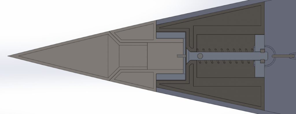
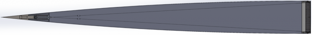
Our main parachute is round with a hole in the middle. This shape leads to a high drag coefficient, allowing for a smaller parachute. Both main parachute and drogue are stored within the nose cone. To eject them, the nose cone gets separated from the main body. To do so, we developed a mechanism we nicknamed “Slingshot”.
A tensioning line goes from the bottom coupler all the way to the top of the nose cone. The tip of the rocket can be taken off, allowing for access to a screw. By screwing this screw a to the tensioning line connected plate can be pulled up, tensioning it. As a result, the nose cone is stable on top of the main body. Upon reaching apogee, line cutters cut the tensioning lines. Springs within the coupler then separate the nose cone from the main body, which leads to the parachute being ejected. To ensure separation, two separately activated line cutters are implemented. The following video shows the mechanism in action using a pyrotechnic line cutter: https://www.youtube.com/watch?v=tTuxokPkKEM&feature=youtu.be&t=50
Tanks
The tanks are structural components that serve purposes in both the propulsion and aero structures subsystems. This design, given the selected tank materials and type, enables a lighter rocket, because there is no need for an additional airframe tube. Type IV tanks use a plastic liner in which the propellant is stored. A full carbon fiber composite overwrap carries the structural loads. These tanks require a complex bulkhead, which is a machined aluminum part, and is bonded in between the plastic and the composite structure.
[table id=19 /]
The nitrous oxide tank will be positioned above the ethanol tank, this provides a slightly higher centre of gravity location. The tanks are independent vessels and will be mechanically connected with a coupler. Since the tanks are structural airframe components, it is not possible to lay any wiring or piping on the outside of the tanks without proper containment (fairings, high temperature tape, etc.). At this stage, it is desirable to avoid external wiring and plumbing lines, since the exact aerodynamic conditions (especially heating) are unknown or known to a lesser extent than the tank internal conditions. This means that in the current it is necessary to route certain plumbing and the datacom lines through the tanks. At least one nitrous oxide pipe must pass through the ethanol tank and one electrical data cable through both tanks.
The sealings of the pipes must be executed in a way that ensures there are no unexpected structural loads because of lengthening in consequence of pressuring the tanks. This will be ensured by seals that are flexible in axial direction on one side of the bypass tubes. The ethanol will be pressurized from a nitrogen tank below through a rising pipe and the nitrous oxide will be pressurized from above without a rising pipe. For both tanks there is monitoring for pressure and for temperature and a pressure relief burst disc on each tank to make sure critical pressure is never reached. It will be necessary to cool down the tanks when they are filled, especially the nitrous oxide tank is very temperature sensitive and should never reach critical pressure. This cooling process is very easy to achieve simply by letting the nitrous tank continuously vent to atmosphere. Even in temperatures as high as 48°C, such as at Spaceport America, UTAT has previously managed to chill the nitrous tank via this approach. Insulative approaches will also be investigated to control the nitrous temperature after disconnecting the fill system and closing the vent.
Baffles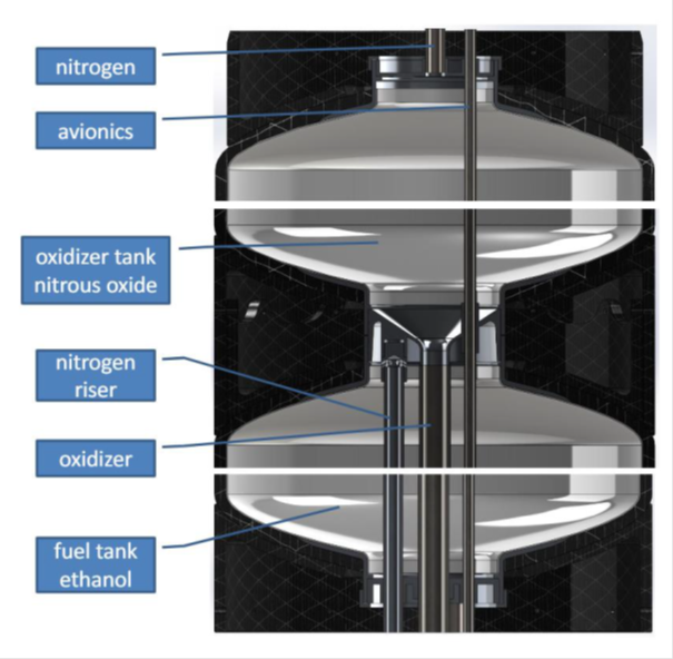
To reduce the movement of a free fluid surface (‘sloshing’) on the dynamic behavior of the tank, it is necessary to install baffles into the propellant tanks. This is especially critical for fluids like nitrous oxide, whereby a large surface area to volume is required to quench any possible localized spontaneous decomposition (an effect of adding baffles).
Avionics Cable Duct
It is necessary to connect the upper and the lower avionics by electric wiring. For this reason, a cable duct with 6-7mm internal diameter will be installed. This pipe will pass through both propellant tanks. To prevent any static charge relative to the tank walls from building up on the duct, the duct will be made from (slightly) conductive material like carbon fiber or metal and will be electrically connected to the tank.
Safety
As with any space company, the obvious relevance of the safety of members of the TU Wien Space Team also gives a high priority to quality and risk management. To make these areas accessible for the whole team, the weekly Safety Circuit was created, which serves the purpose of a continuous improvement process. For example, a safety and procedures manual was created, which will be tested in the Spaceport TXV project and later be adopted by the entire TU Wien Space Team. Another important point in this context is the further development of a knowledge management system, which aims to protect the knowledge of the team against employee turnover and make it accessible to all team members.