As reported in an earlier blog post the second launch of the rocket The Hound in September 2019 was not successful again. The following report documents the findings of a profound analysis of the launch.
Concept overview
First, some necessary details of the configuration of The Hound are introduced in order for readers to be able to follow the discussion of the results later on.
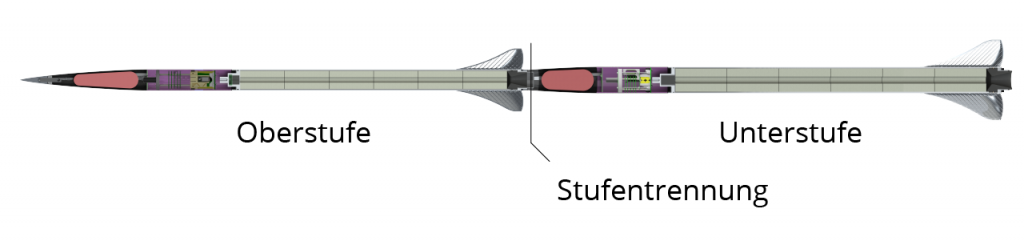
The Hound is a two-staged sounding rocket. The booster stage is ignited at the launch pad and lifts the rocket during the initial phase of the launch. Shortly after the burnout of the booster motor, the sustainer stage is separated from the booster, initiated by the sustainer’s onboard avionics. The sustainer coasts into the thinner upper atmosphere, then the motor of the upper stage is ignited.
 The sustainer uses a two-staged recovery system. Its main flight computer FMS (Flight Management System) detects the apogee and separates the nosecone from the rest of the rocket. An Altus Metrum EasyMega serves as a backup for the first recovery stage. To locate the rocket after the landing in case of a failure of the FMS an independent device, a Featherweight tracker, is located in the nosecone.
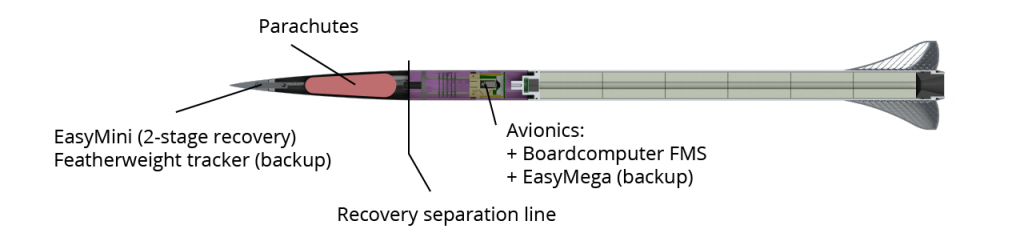
The nosecone is connected to the rest of the upper stage and the drogue via an aramid cord. First, the drogue should stabilize the rocket during reentry into the atmosphere and decelerate the rocket before the main parachute is opened. The main parachute is retained inside the nosecone and is released at a predefined altitude by an Altus Metrum EasyMini actuating a CYPRES linecutter.

The recovery of the booster stage is initiated by an identical FMS. An Altimax Simply from rocketronics.de serves as a backup for the flight computer.
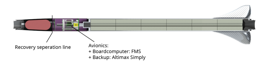
In contrast to the sustainer, the main parachute is deployed together with the drogue, but is deployed in a reefed state. Then, the Jolly Logic Chute Release releases the main chute at a specific altitude.

The flight sequence 2019
So much for the theory! Last year a miswired safety device inhibited the ignition of the upper stage motor (link). But this year’s malfunction has proven much more difficult to pinpoint.
This is what we know with certainty at this point from observations or analysis of the recorded flight data:
T=0s: liftoff from the launch tower
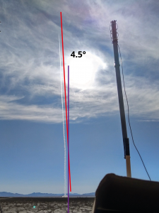
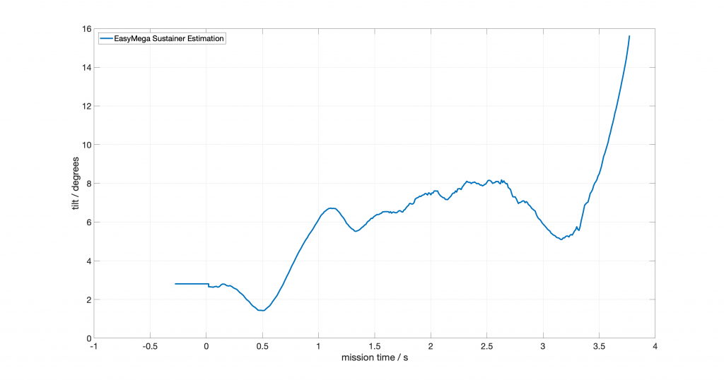
T=0.75s, 80mAGL, 180m/s: The rocket is influenced by crosswinds and tilts approx. 4.5 degrees.
T=1.3s, 230m AGL, 330m/s: Passing the speed of sound. This leads to a pressure fluctuation measured by the pressure sensors, which is a well-known phenomenon and shown by all flight computers.
T=3.5s, 1700m AGL, 800m/s: The angle of attack of the sustainer stage increases rapidly to 16 degrees. This yields in a disintegration of the mechanical structure, which is torn off the motor casing. As a consequence, the avionics bay is damaged and the power supply is disrupted. From now on, the flight computers (FMS and EasyMega) are not powered any more and neither transmit nor record any data.
T=8s: The sustainer reaches its apogee of about 2200m. The featherweight tracker in the nosecone still transmits its current position.
T=27s: The booster stage reaches its apogee of about 6000m. The apogee is detected by the FMS, which ignites the separation charge. The booster stage descends at about 120m/s, which is the simulated velocity of a ballistic flight profile. This means that the separation or the deployment of the parachute was not successful.
T=75s: The booster stage hits the ground of the desert. Due to a malfunction of the avionics no position data was sent after T=13s and the impact spot still remains unknown.
T=80s: The avionics bay including the still connected nosecone of the sustainer impacts the ground. The Featherweight tracker sends its position until shortly before the impact.
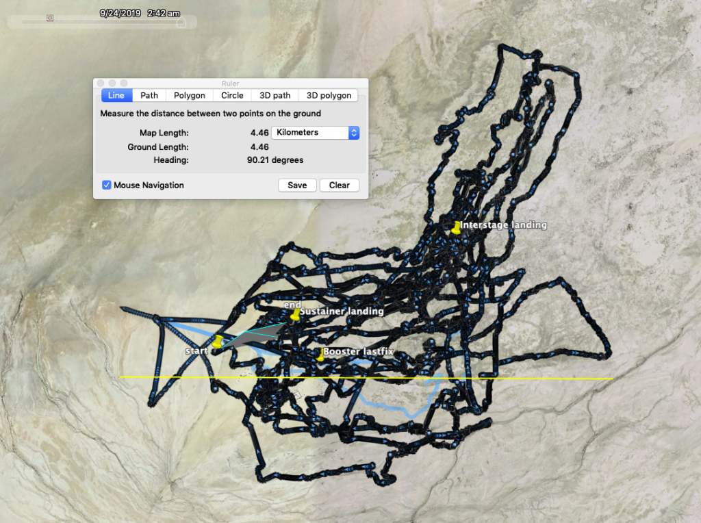
The sustainer’s avionics bay was retrieved shortly after the launch. As can be seen in the following picture, it left an impress on the soft surface. At least the nosecone was close to the avionics bay but without the parachute being deployed, or more likely, even still connected and separated only during the skew impact. Due to the disconnected power supply no separation, i.e., recovery, was possible at the apogee. If the upper stage had already separated at T=3.5s while traveling at supersonic speed, for sure the aramid chord would have been torn off and both parts would have been landed separately.

Furthermore, the aluminium screw connection to the motor casing, which was glued to the inside of the glass fiber tube, was missing. The damage on the tube shows that it broke between the glass fiber tube and the motor casing due to a bending moment (left tube undamaged, for comparison).

After an intense two-day search only the interstage coupler was found. It had landed in a distance of 4km to the nosecone of the sustainer. The aramid cord had ripped apart during the flight and the parachute was missing, too.
Measured data


Further learnings and comments
- The FMS continuously buffers measurement data in RAM before it is written on the flash memory. This enables that data before the detected liftoff can be recorded without the need of starting the recording manually. As a consequence, after power was lost, data residing within the buffer but not yet written to flash was lost. This resulted in the loss of roughly 1s of FMS data before the breakup happened. The EasyMega recorded approx. 1.5s longer than the FMS.
- The non monotonic curve of the barometric determined altitude of the booster stage during ascent points to any influence on the flight of the booster stage itself. Furthermore, the measured apogee of 6000m AGL was clearly lower than that of last year’s nominal flight up to 8000m AGL.
- Remnants of a fired separation charge were found inside the interstage coupler. This means that the coupler was still connected to the avionics bay of the booster stage when any charge was ignited. Furthermore, the coupler does not have any mechanical damage. It is therefore assumed that no mechanical overload (e.g., bending moment) was acting on the coupler before separation.
- The transmitted data of the booster’s FMS suggests that it detected all flight events correctly. The separation charges of the FMS were not ignited before the apogee.
- No measured data like angular rates or acceleration data from the booster stage is available, because the stage has not been retrieved yet. Therefore, it is not possible to determine whether the booster and sustainer stage were still connected when the sustainer broke apart.
- Due to the desert’s MSL of 1100m a plausibility check of the Altimeter Altimax Simply always fails with its standard firmware. Due to this reason, the launched booster stage in 2018 did not have any backup. In 2019 a custom firmware was used, enabling the usage of the Altimax Simply as a Backup. It was configured to should ignite its deployment charge 2 seconds after the detected apogee. It is noticeable that the increase of the angle of attack of the sustainer happened about two seconds after the sonic artefacts of the measured pressure. This could have led to a false detection of the apogee and separation of the rocket by means of the Altimax Simply at T=3.3s.
- The breakup of the rocket happened right at burnout of the booster motor.
Analysis: Possible causes
The anomalies during the flight can have different and non-correlated causes.
The analysis shows the following two failure cases, which can explain all observations in a plausible way:
- Due to the early detection of the apogee by the backup Altimeter Altimax Simply (see above) the booster stage separates at T=3.5s. The interstage coupler is still connected to the sustainer at this moment. Because of the high velocity (Mach 2.4) the parachute is not deployed but the aramid chord, which connects the coupler to the sustainer, is torn immediately. The sustainer experiences a radial force and therefore, noticeable torque. This increases its angle of attack and the mechanical structure breaks due to the bending moment. Because the coupler was already missing during the ascent of the booster stage, the apogee of the booster was decreased due to the increased drag.
- Some aerodynamic force (e.g., due to crosswinds) increases the angle of attack of the overall rocket. The airframe of the sustainer breaks at the upper end of the motor casing and initiates its descent independently. The sustainers’s motor casing is still connected to the booster stage. This combination is stabilized aerodynamically and ascends further together. Due to the slightly higher angle of attack the airspeed is decreased drastically, which explains the lower apogee of the booster stage compared to last year’s launch. After the ignition of the separation charge at apogee – the sustainer’s motor casing is still connected to the booster – the weight of the sustainer tears the aramid chord connecting the booster with the interstage. The parachute is torn away, too, and the booster descends in a ballistic flight profile until the impact on the ground.
Outlook
The team drew its lessons from this years launch campaign: delivery of the motors has been delayed, faulty mechanical integration of the two rocket stages required repairs, RF link performance was reduced due to the moist salt-rich soil, and finally the unsuccessful launch at the last minute.
With these learnings in mind, the concept is currently revised and adaptations are made to increase the chances of a successful launch in 2020.
Acknowledgements
At this point the team wants to give thanks to its partners and sponsors. Without them this project would not be possible.
