resources
open source
One of the goals of TU Wien Space Team is to make aeronautics and space more tangible and accessible for the public. That is why we are committed to share our work and results under free licenses: code & documents
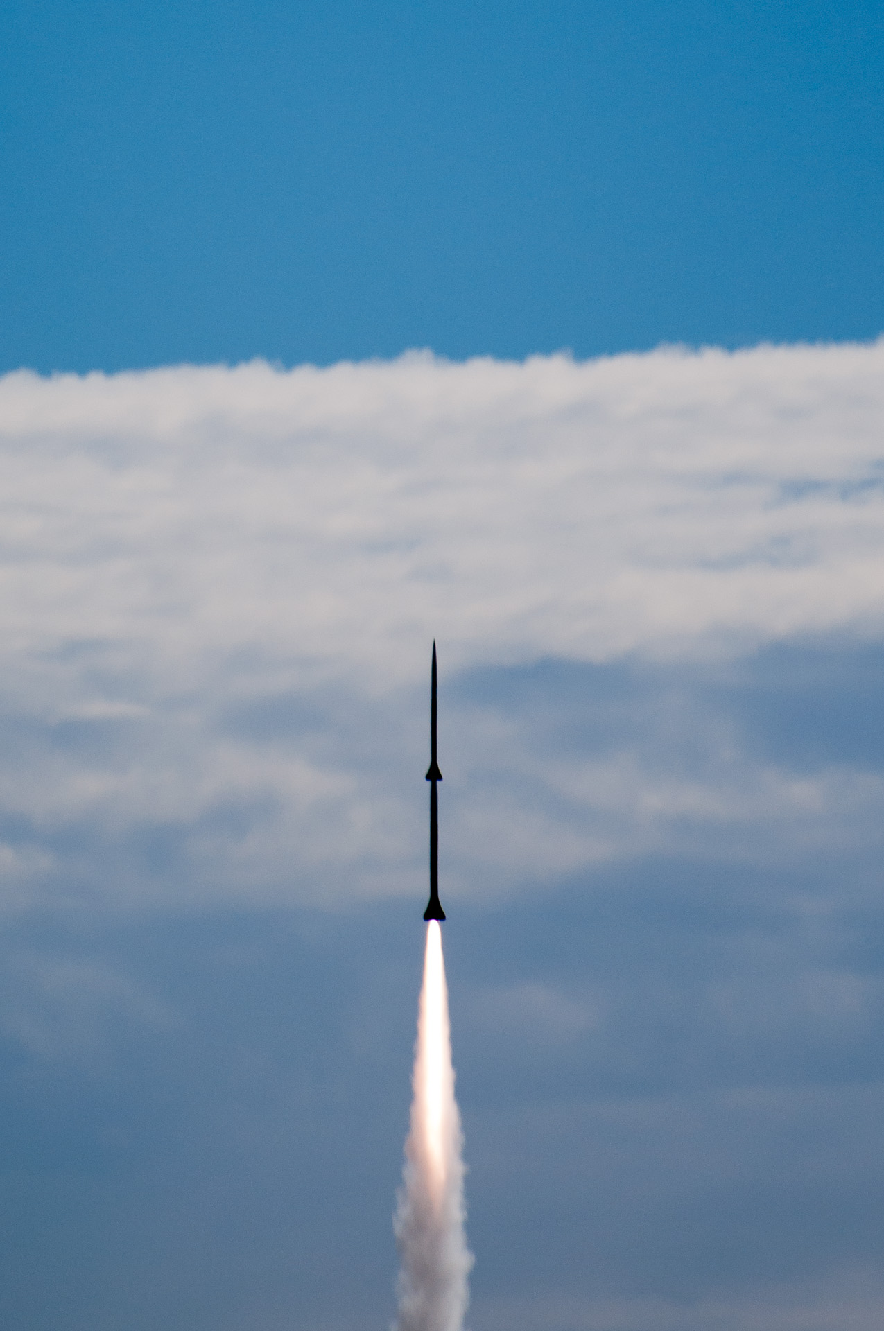
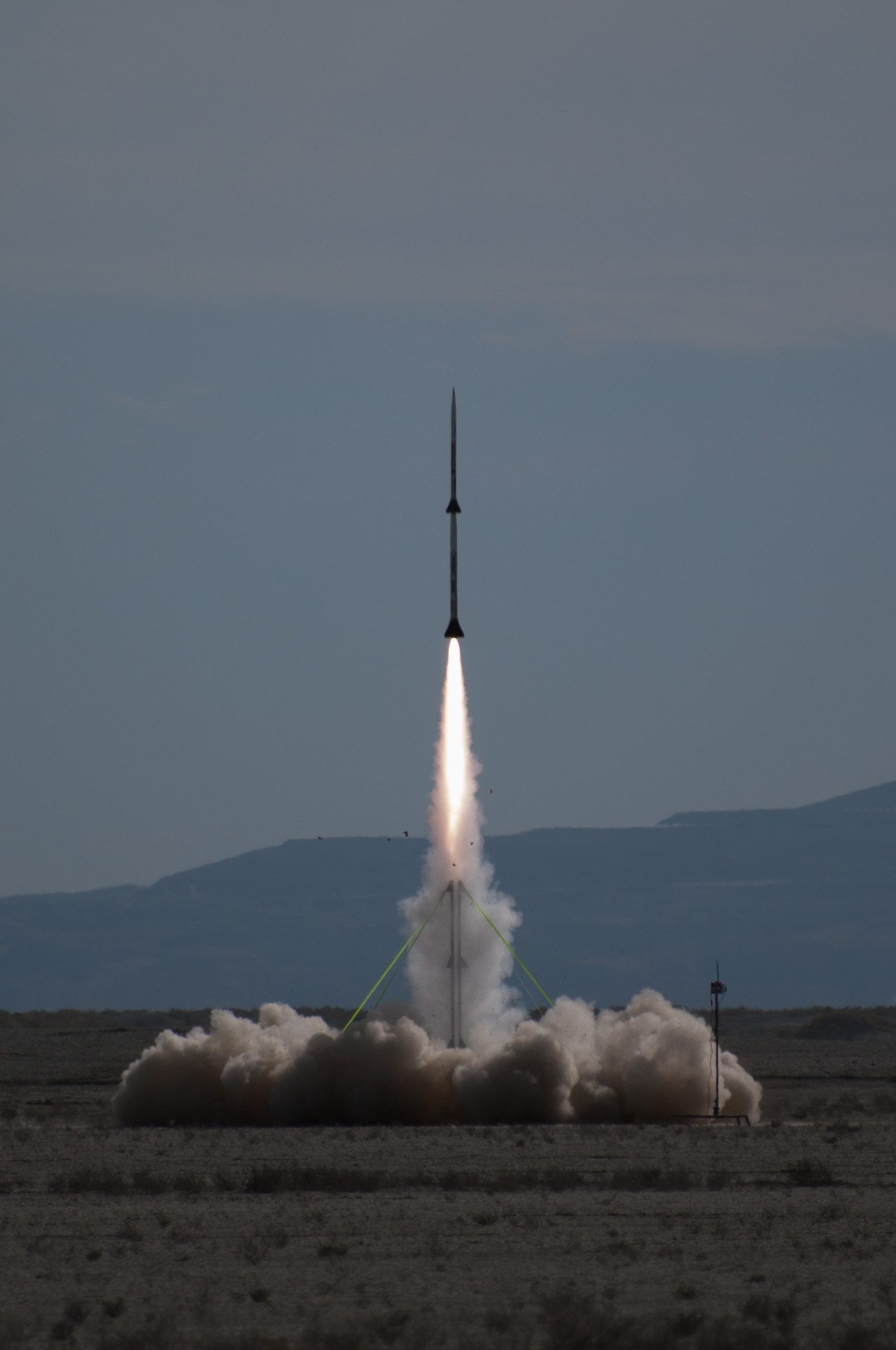
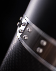
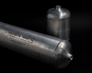
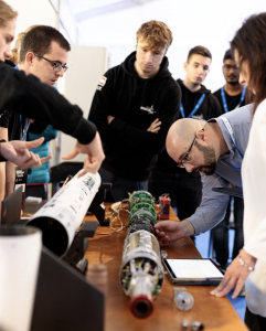
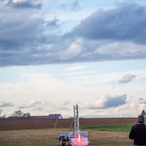
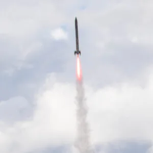
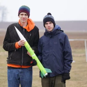
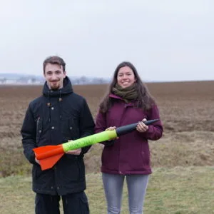
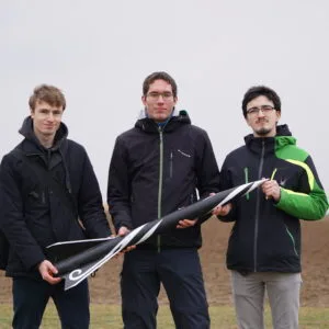
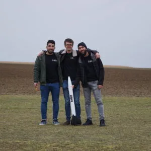
High quality press photos
Press use of these pictures is free of charge. Please make sure to give credit as suggested below.
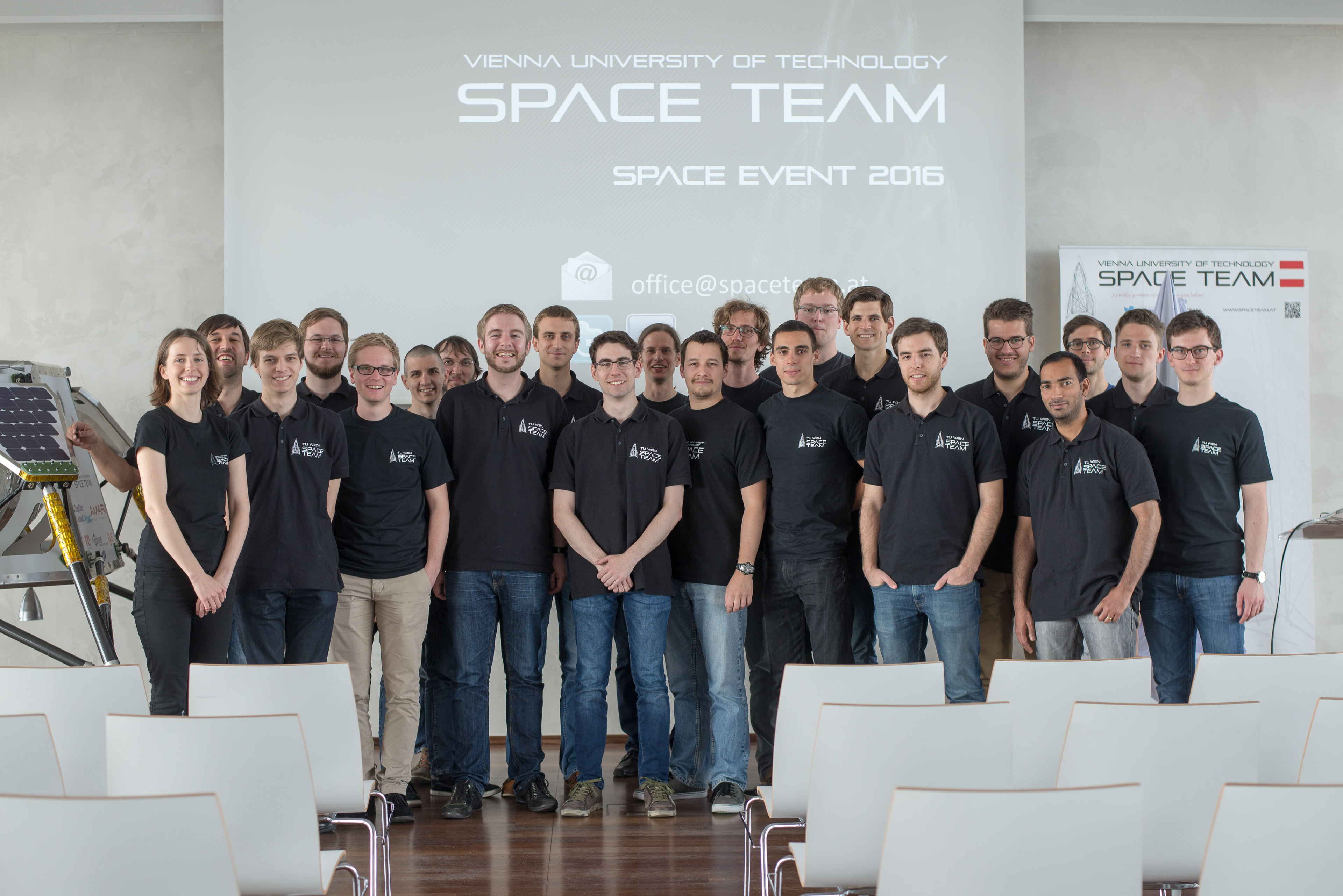
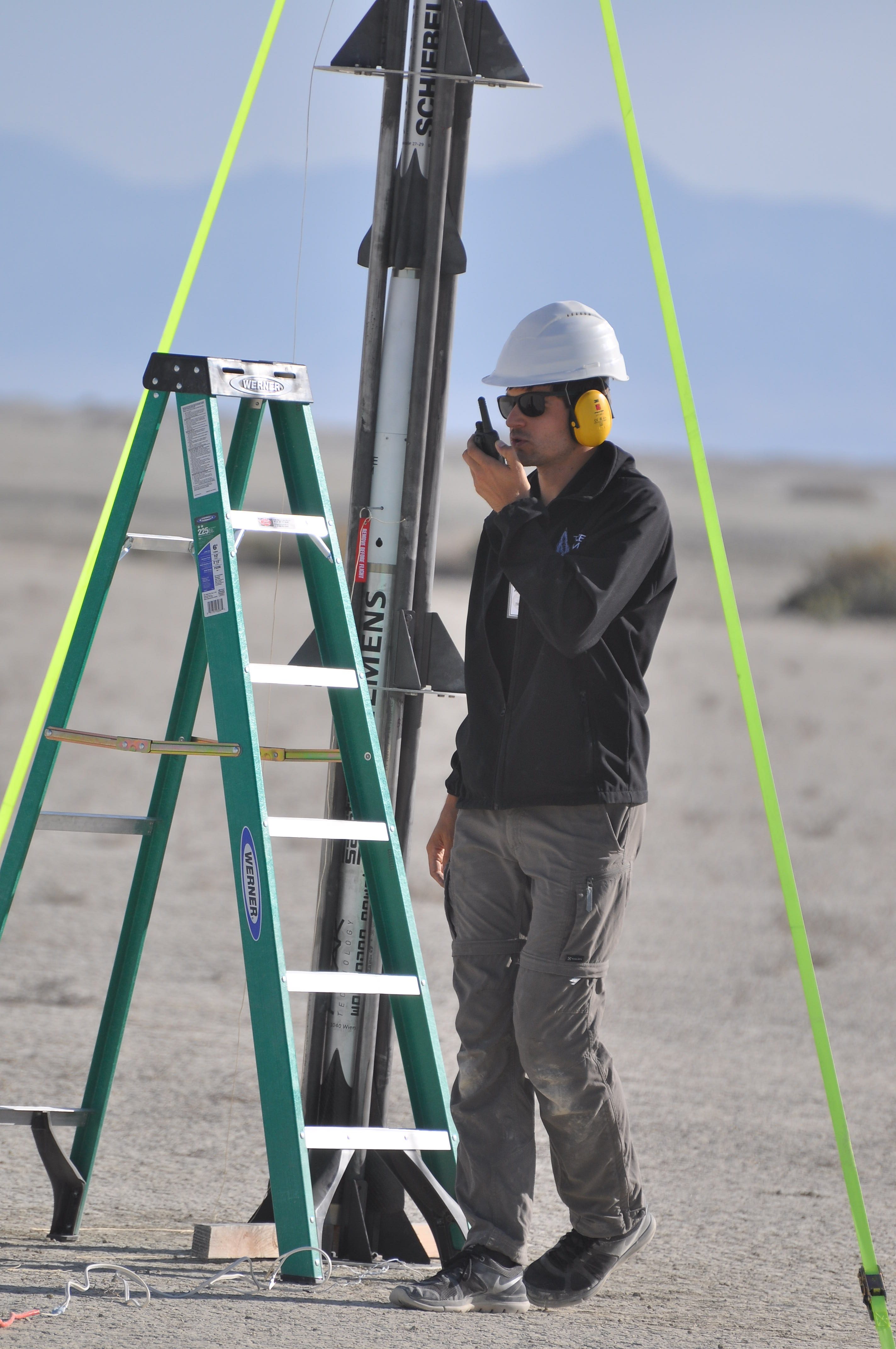
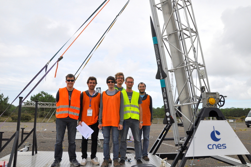
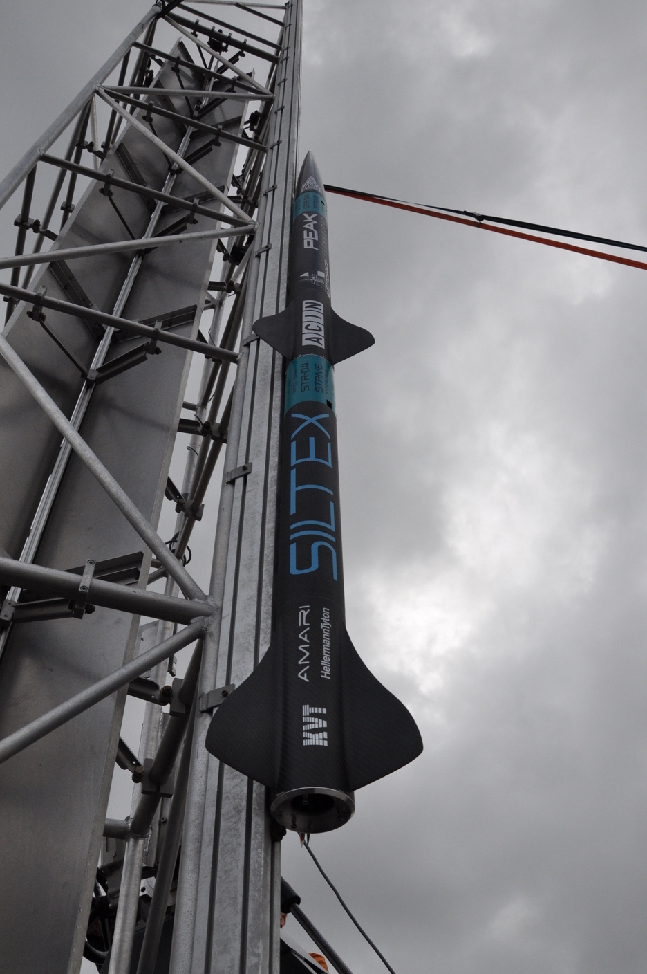
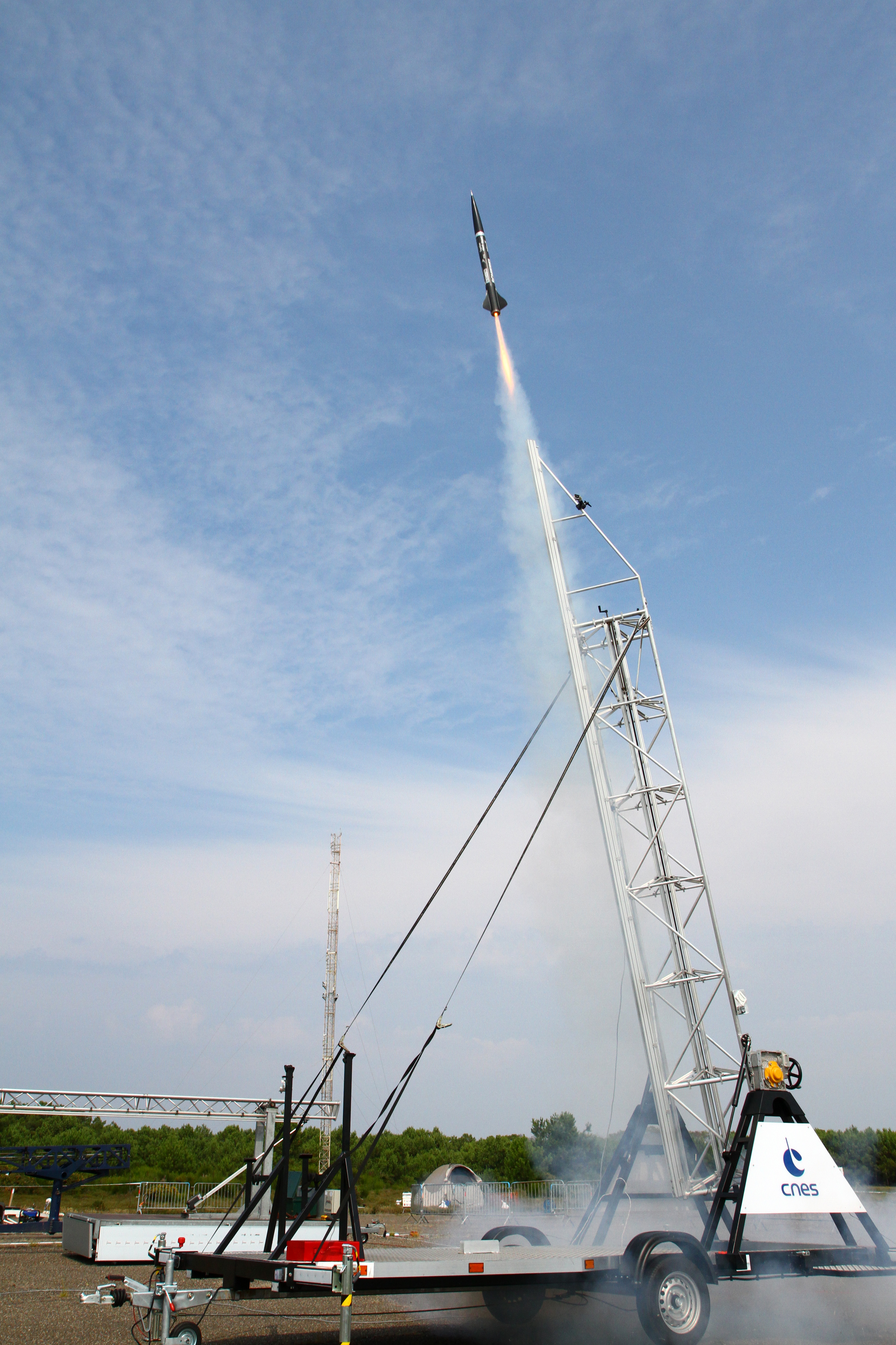
Pressefotos


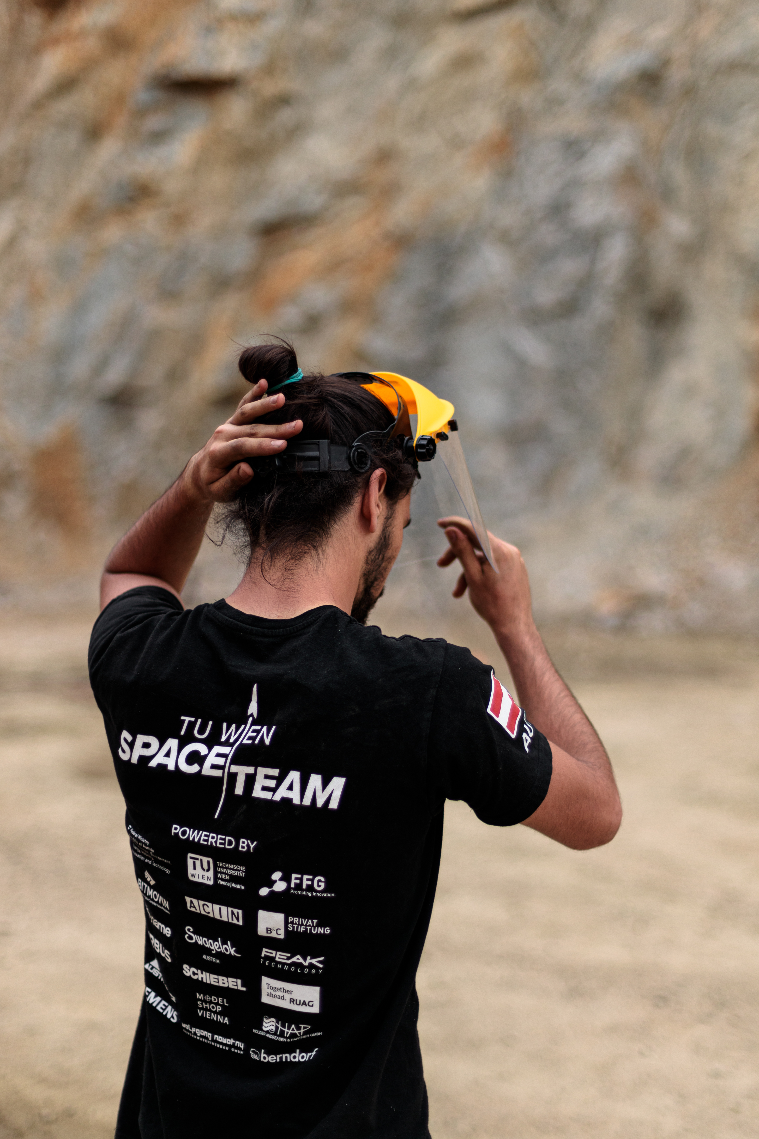


Student Aerospace Module
We offer the course “Student Aerospace Module” at TU Wien.
Student Aerospace Module
With the goal of an even closer long-term partnership with the TU Wien we can now offer students a new field of specialisation in aerospace engineering. The Student Aerospace Module was introduced in 2020. Students of Mechanical Engineering (E033245) and Mechanical Engineering – Management (E033282) now have the opportunity to select either the Student Aerospace Module 1 (7 ECTS) or the Student Aerospace Module 1+2 (14 ECTS) in their bachelor or master studies.
Both modules consist of mandatory courses as well as courses, which can be selected from a pre-determined list. Importantly, every student has to complete the new Student Aerospace Project, which is mandatory for bachelor and master students.
The official description of the module can be found in the respective curricula and on TISS (Link).
Details: Student Aerospace Project (307.502, 5 ECTS)
The project is mandatory in both modules and is written about a topic in the field of aerospace engineering, which is considered relevant in the TU Wien Space Team, and supervised by employees of institutes of the TU Wien. Keep in mind that the number of possible projects is limited by the academic supervisors. Please contact the responsible tutors if you are interested in writing a Student Aerospace Project (contact details below).
If you have any questions concerning the Student Aerospace Module or Project or if you want to write a Student Aerospace Project, please feel free to contact us under the following e-mail adresses:
General information: studentaerospace@tuwien.ac.at
Responsible tutor Alicia Wollendorfer: alicia.wollendorfer@tuwien.ac.at
COMPLETED projects

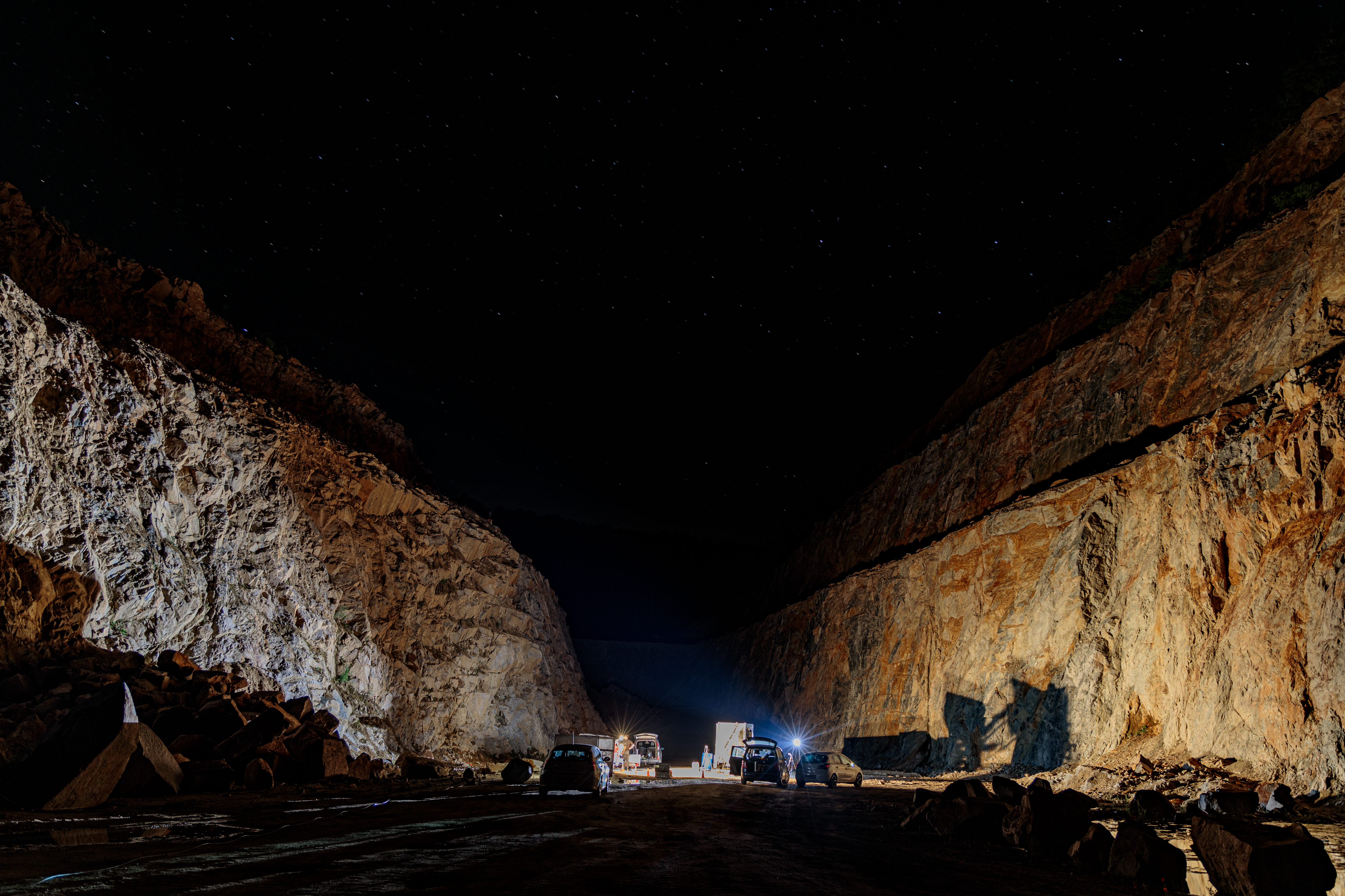
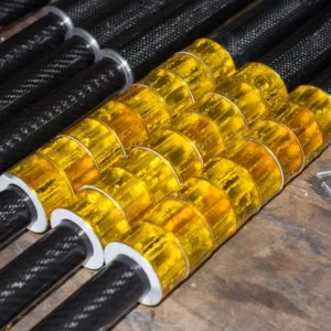
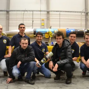
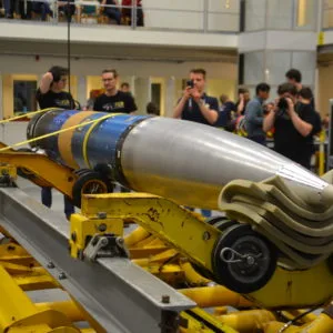
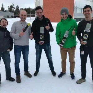
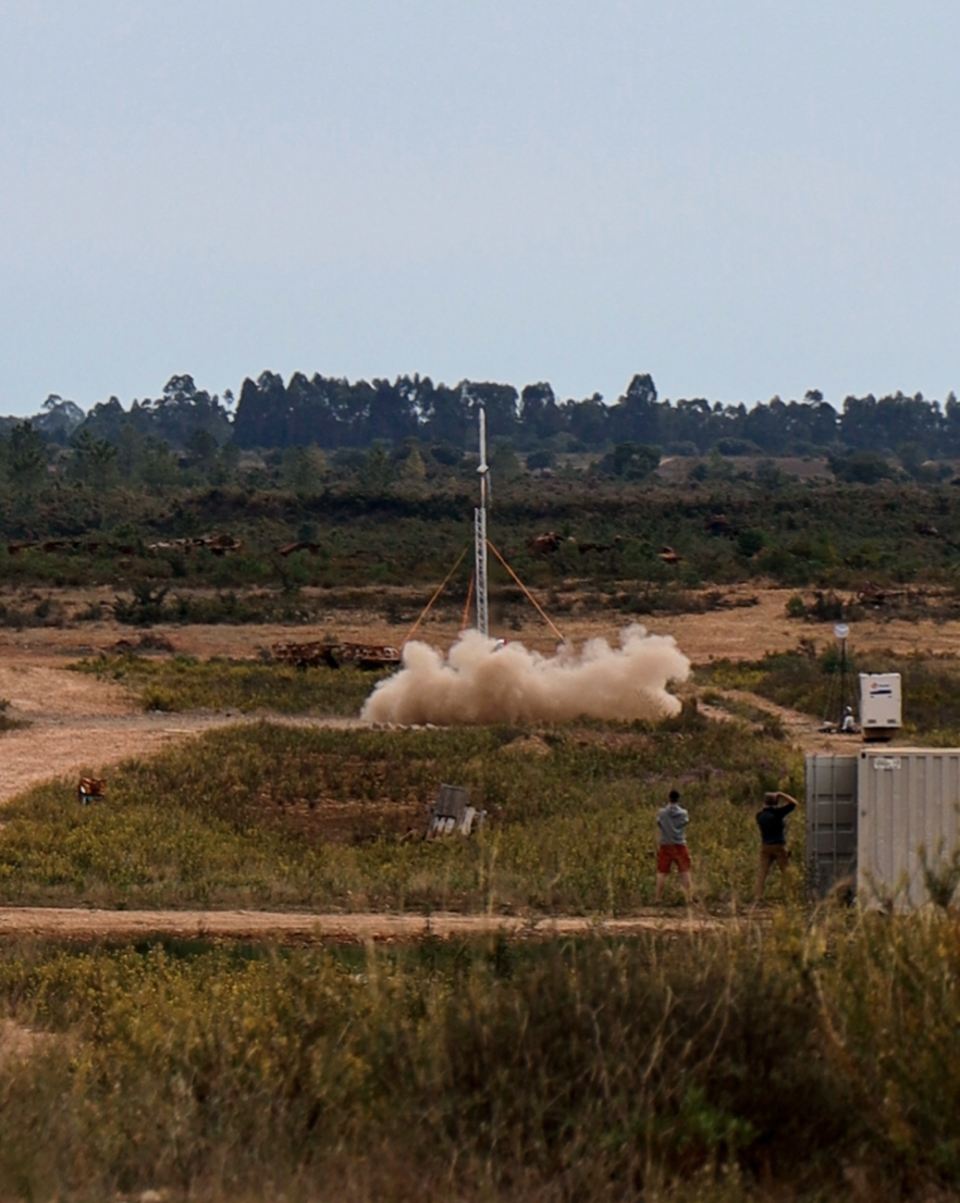
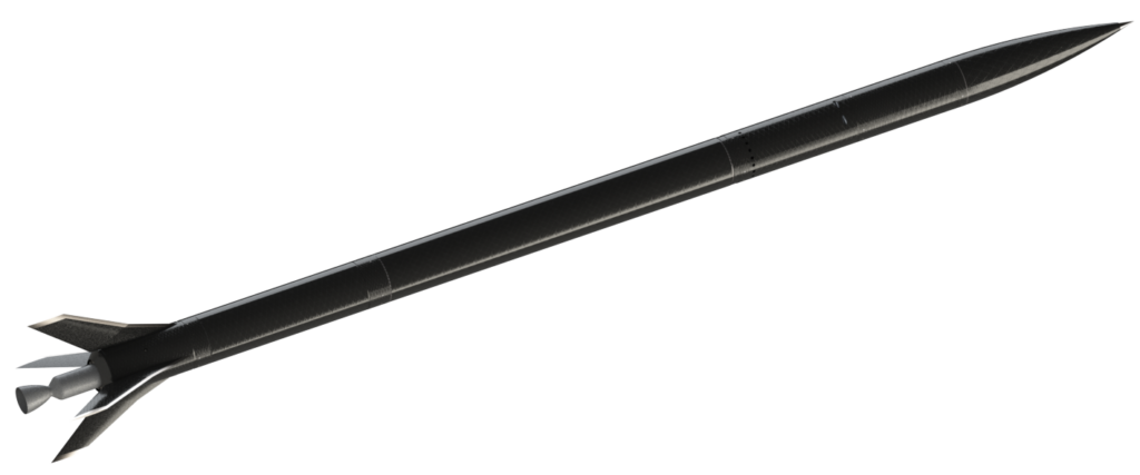
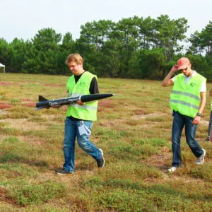
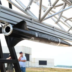
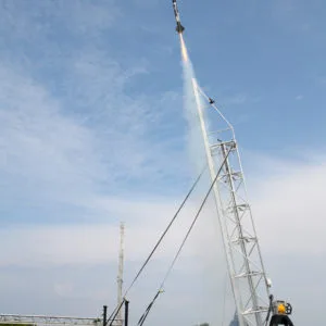
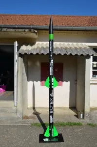
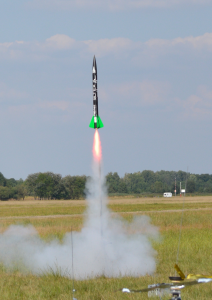
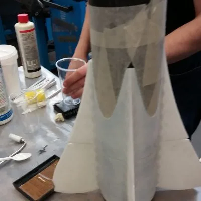
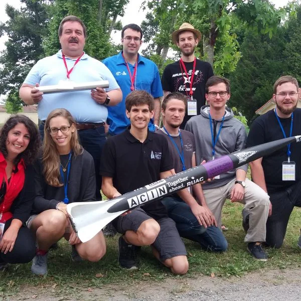
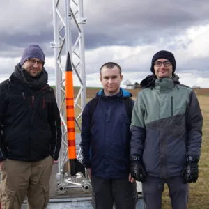
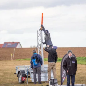
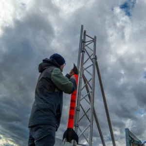
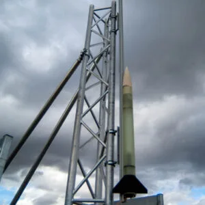
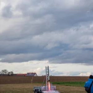
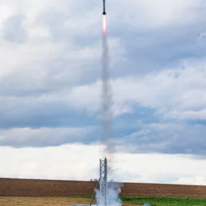
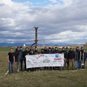
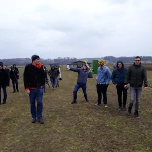
The Hound has built a two-stage solid-fuel rocket to break the European altitude record for student teams and perhaps even reach space in the process.
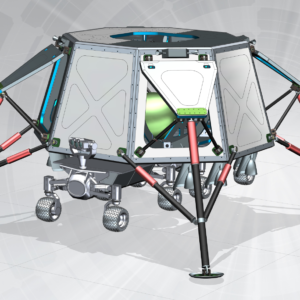
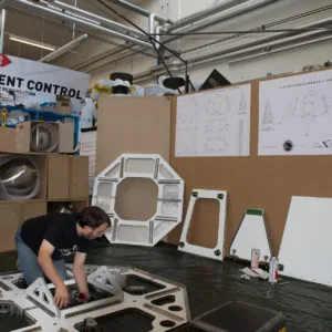
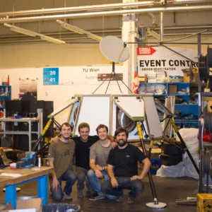
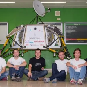
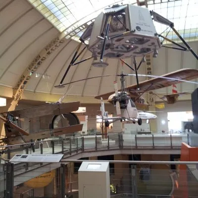
Lunar Lander
Lunar Lander
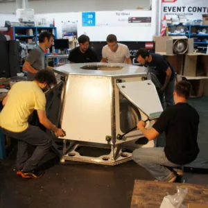
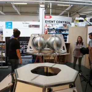
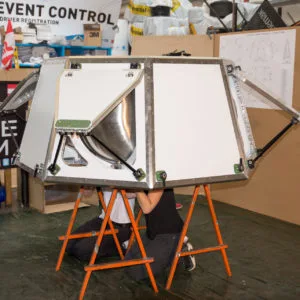
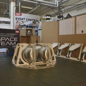
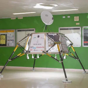
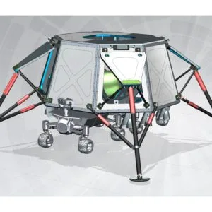
In cooperation with the part time scientists (TM) we have built a lunar lander for the GLXP challenge from may to october of 2014. The main challenge consisted in designing a structure that could withstand the enormous forces at liftoff (8.5 g). During the landing on the moon the remaining momentum must be mitigated and handled by the legs. Because optimizing for weight was of utmost importance, we decided to build the main structure out of aluminium panels with a honeycomb core sandwich construction. This relieves the tanks (which are the main burden at launch with about 500 kg of fuel), distributes structural loads from the legs efficiently (dry mass of about 300 kg, max. fall heigth 5m at 1/6 g) and offers various surfaces for solar panels and cooling.
Basic structure
The full scale prototype we designed and built is about as big as a small car, while massing only 65 kg for the main structure and legs. Base area: 1.7 m * 1.7 m, diagonal over everything: 4 m, height: 1.6 m
Video of the Body Assembly
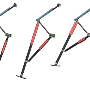
legs ans shock absorbers
The leg structure is an in-house development, which was conceived, calculated and constructed step by step.

Leg and Final Assembly
on display at the vienna museum of science and technology
In April of 2017 the Lunar Landing Module was given to the Vienna Museum of Science and Technology as a permanent exhibit. It can be seen in the aeronautics department.
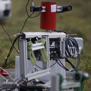
Rocket Tracker T-REX
Rocket Tracker T-REX
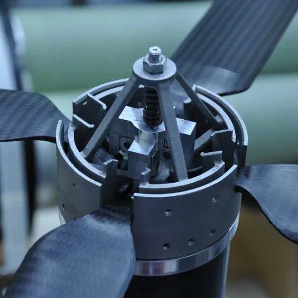
It is our goal to film rocket launches automatically, in high resolution by making use of computer vision. T-REX (Tracking Rocket EXperiments) was started by WüSpace e.V. We collaborate with them on the project since 2019.
How does the rocket tracker work?
The gimbal is pointed at the rocket on the pad. A computer vision algorithm continously registers the vehicles position and reorients the gimbal. The two axes are, depending on the version, controlled by stepper or brushless gimbal motors. As of now the software runs on an external laptop, but it will soon be ported to a single board computer with an AI core.
Prototypes have already been tested on various launch events e.g. Straubing in march of 2020, in Manching or at EuRoC in Portugal.
Not only is the attained footage spectacular, but also very useful for analysing the flights. Especially in the case of an anomaly the high resolution videos are very important.

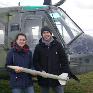
REXUS: Project Daedalus
REXUS: Project Daedalus
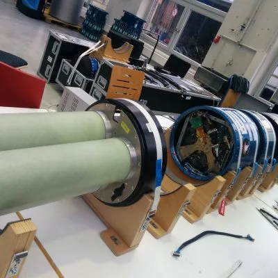
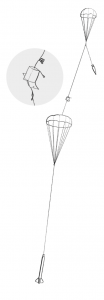
Together with the university of Würzburg, TU Wien Space Team started an ambitious project: Recovering probes that are jettisoned from a rocket without a parachute.
The idea is out there and nobody knows, whether it will work: Tube like probes shall be carried to a height of 75 km with a rocket and return by themselves intact. Should this technology work, it might become an interesting tool for meteorology in the future.
the idea
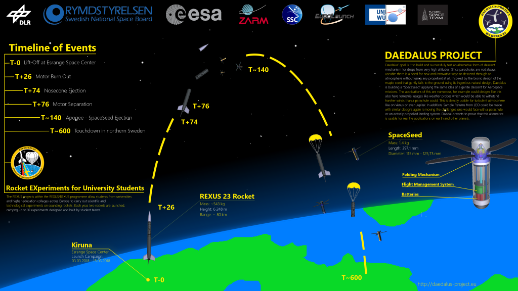

The idea for the new probe reminds of a maple seed that glides slowly aground with its wing.
The tube like probes, we call Space Seeds have wings are deployed after the machines are jettisoned and slow them down.
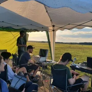
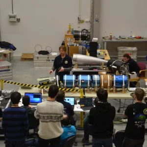
Project presentation by Clemens Riegler at the 2018 space event.
our contribution
We developed the onboard computer and the ejection mechanism.
the ejection mechanism
During the project 3 Space Seeds were started simultaneously. During the start and ascent they were located in the nose cone of the rocket.
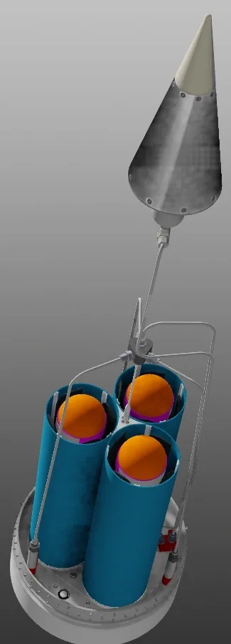
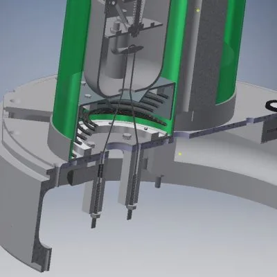
Note that the wings are folded in during ascent. While the Space Seeds are housed in three fibreglass tubes, these also form part of the ejection mechanism. The probes sit on a tensioned spring which is held back by a steel cable. Special care was taken while selecting the materials to guarantee high strength at low weight.
The steel cables were cut by a pyro cutter at the apogee (75 km) thus releasing the Space Seeds.
Onboard-Computer FMS3D
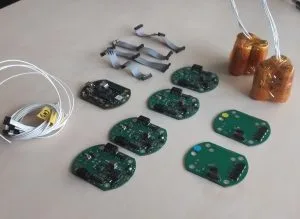
As flight computer we used an adapted version of our flight management system. Among other things we had to adapt the power supply, because NiMh batteries had to be used due to regulatory constraints. Because we launch in Sweden in winter the batteries are prewarmed on the launch pad to attain full performance.
Communications between the rocket and the Seeds are handled by XBEE short range modules. Additionally iridium satellite modules are used to transmit the final position after landing.
REXUS/BEXUS
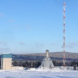
“REXUS/BEXUS” is a cooperation between DLR, the swedish national space board and ESA. Every year REXUS launches two rockets in Sweden that carry student experiments to aheight of about 80 km.
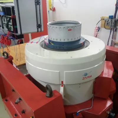
As a part of the campaign specific milestones need to be reached and tests need to be carried out in DLR, ZARM and SNSB labs.
Launch campaigns
march 2018
The launch of the REXUS23 rocket including the Space Seeds was actually planned for March 2018 in Kiruna, Sweden. After the student teams arrived in Kiruna their experiments were integrated into the rocket and various tests were performed. This was to ensure that the launch procedures would take place without a hitch and to ensure that the experiments would not influence each other nor the launch itself.
After a faulty start of REXUS24 the launch campaign was stopped and the launch of REXUS23 was delayed by a year.


March 2019
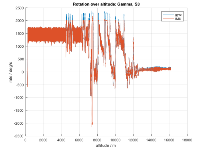
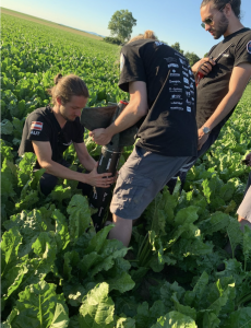
In March 2019 it was finally time for REXUS23 to launch before REXUS 25/26. The three Space Seeds were brought to an altitude of around 75 km and released. The seeds remained in radio contact throughout its flight and were salvaged the next day with a helicopter.


Ejection Video.
The analysis of the recorded data proved that the Space Seeds stabilised themselves during reentry into the thicker atmosphere as planned and began to rotate. This rotation decelerated the Seeds from around 800m/s at an altitude of 35km to around 25m/s during landing, which the Seeds survived without damage.
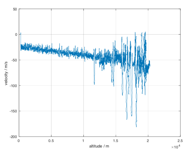
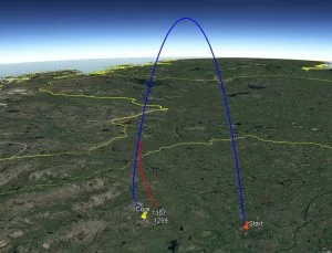
The Space Seeds landed around 33km away from the launch site. The following image shows the flight parabola of the REXUS23 payload section and the path of the Space Seeds, which already had a GPS connection at an altitude of 15km.
Conclusion
Project Daedalus was a complete success. Many smaller successes for us were reached with this project such as:
- The TU Wien Space Team were able to take part in the German-Swedish REXUS/BEXUS program
- Members of the Space Team were able to attend two launch campaigns in Kiruna, Sweden, and create new international contacts
- The boardcomputer FMS, which has been part of our rocket projects such as STR and The Hound, was used in Daedalus and brought to an altitude of 75km.
- article: ESA PAC Symposium 2019
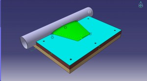
DISCO One (Konzept)
DISCO One (ConCept)
CubeSats are a key technology enabling cost-efficient deployment of many applications in space such as earth observation, communication and technology demonstration. Most of these applications share an extensive demand for data-downlink from the satellite to a ground station. High downlink data-rates increase the requirements towards space, weight and power (SwaP), a valuable good on any CubeSat mission. Furthermore, traditional (amateur) radio frequency bands experience heavy bandwidth allocation and trends towards the utilization of shorter wavelengths are already visible in communication systems using S-, X- and Ka-band frequency ranges.
The following concept proposes to reduce the communication wavelength further towards optical frequencies, effectively resulting in free-space optical communication for CubeSats. Optical frequencies allow minimized divergence angles, therefore high-energy efficiency, high data-rates and no issues with frequency allocation and bandwidth restrictions. However, the particular requirements of this concept introduce many challenges for CubeSat-sized satellites. Especially pointing precision and the resulting specification for the ADCS as well as the necessity to provide power for the carrier signal (the laser beam), have prevented the utilization of this technology’s potential. To overcome these challenges, reflective free-space optical communication has been proposed already in the nineties. Here, all energy intensive, moving and complex components are moved to the ground station, which in general does not face any limits compared to the satellite.
An earth-based, high-power laser is tracking the passing satellite by means of a telescope system and provides the carrier signal for this communication concept. A retro-reflector at the satellite reflects the light directly back to the ground station. An optical modulator attached to the retro-reflector modulates the reflected light and therefore enables an optical downlink. This assembly of retro-reflector and modulator is called modulating retro-reflector (MRR). Using this technology data is transmitted from the satellite to a ground station with just a fraction of the energy that would be necessary to operate a radio transmitter.
DISCO One adapts and implements this concept of reflective optical communication for CubeSats and aims for the proof of concept via an in-orbit demonstration using a single unit satellite. The used MRR system is based on simple LCDs, which are the key component of the proposed system and promise data-rates up to 1 kbps. The main contribution of this concept is to give a system overview and present the concept of the satellite. DISCO One focuses on a simple, robust and long-lasting implementation of the satellite as well as the proposed optical communication system. As it is based on a 1U CubeSat platform, available energy as well as space are limited significantly. The proposed electric power consumption of the full satellite including the MRRs is below 1 W on average, while the communication module only consumes 0.2 W at maximum.
In summary, the goal is to verify the design of a low-cost optical downlink for small satellites which can then be further developed into a re-usable system and utilized e.g. by universities and the industry to increase data-link budgets and decrease energy requirements of future satellite missions.
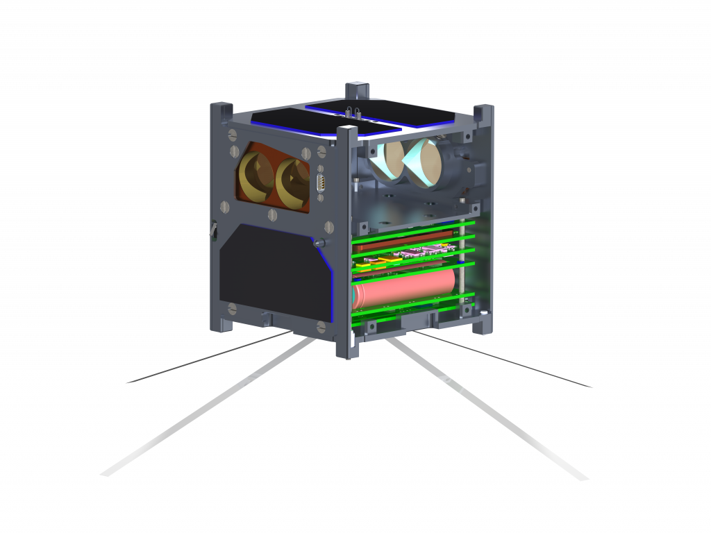
Figure 1: Model of DISCO One
DISCO One consists of the following subsystems:
- ADCS – Attitude determination and control system
- EPS – Electrical power supply
- COM – Communication module
- MRR – Modulating Retroreflector
- OBC – On-board computer
Unfortunately, the idea of this CubeSat remains as a concept and was never implemented due to issues during the realisation of the MRR. Except for the MRR, all other subsystem components were developed.
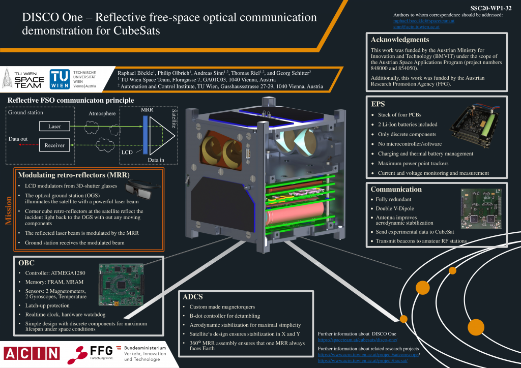
Figure 2: Poster, which was presented at the 34th Small Satellite Conference (www.smallsat.org).
Pegasus
Pegasus
The Pegasus satellite has been in orbit around the earth for several years now. Its current position and measurement data can be viewed live here!
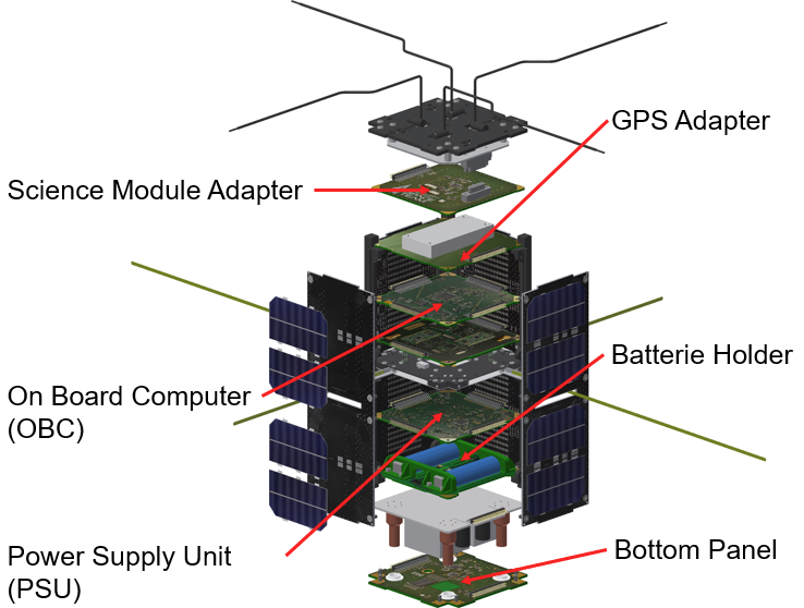
The TU Wien Space Team developed, in collaboration with FH Wiener Neustadt and the Space Tech Group (STG), a CubeSat for the project QB50. The goal of this project was to internationally develop 50 micro satellites of dimensions 10 cm x 10 cm x 20 cm which were sent to space 2017.
The Space Teams main task was to develop the Power Supply Unit (PSU) and the integration of the Boardcomputer (OBC). The PSU is taking care of the power supply from solar cell to electric load while the OBC is handling the data from the sensors and RF module while taking care of the software for attitude control and microthrusters. The Space Team also developed the energy management system, which is in charge of shutting down defect components in order to maintain the efficiency of the rest of the satellite. Modules for the connection of the scientific unit and the GPS modules were implemented. The TU Wien Space Team also developed the software and hardware of the bottom plate which has a camera module which can take pictures from space.
The TU Wien Space Team has designed and developed vital components for PEGASUS, which was brought into orbit by an Indian rocket in June 2017.
First signals were received on the first passes over the ground station! All modules from TU Wien Space Team are working nominal from then on! See http://spacedatacenter.at/pegasus/ for actual data.
The majority of the Pegasus Hardware was developed and built at TU Wien Space Team:
- Power Supply Unit (PSU)
- OnBoard Computer (OBC)
- battery holder including thermostat
- Bottom Panel, camera system and Service-Interface of PEGASUS
- adapter modules to GPS and science module

GATE
GATE
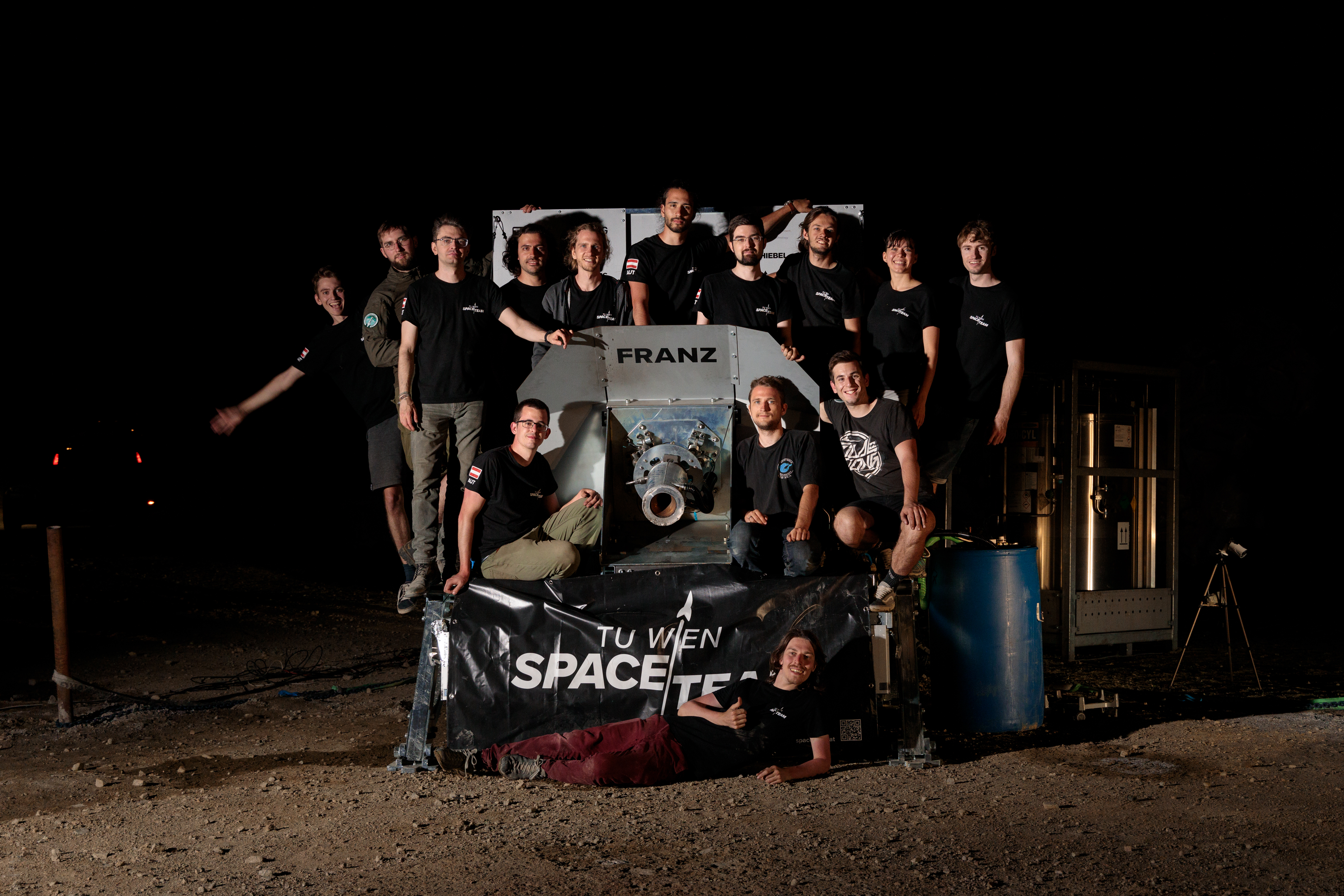
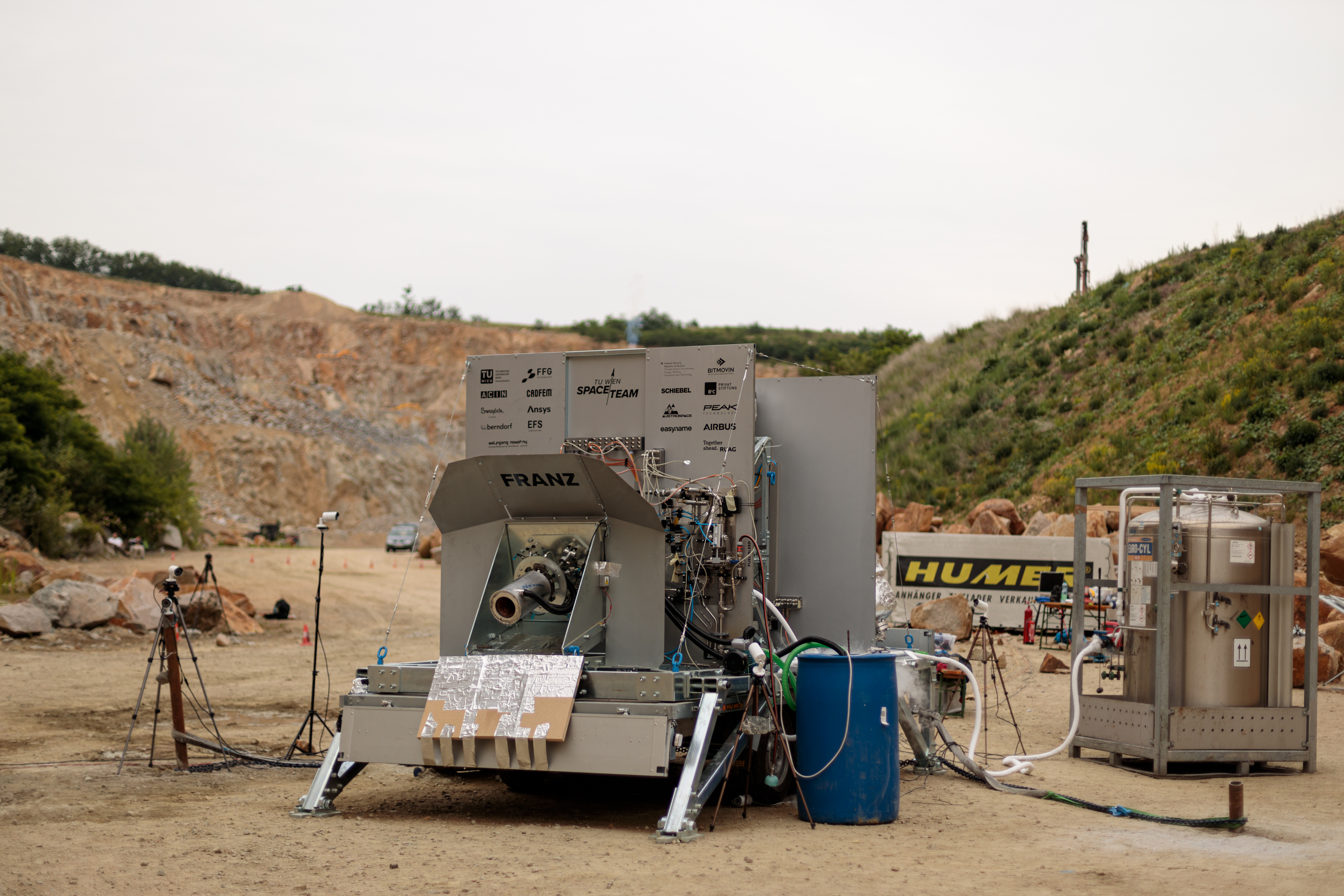
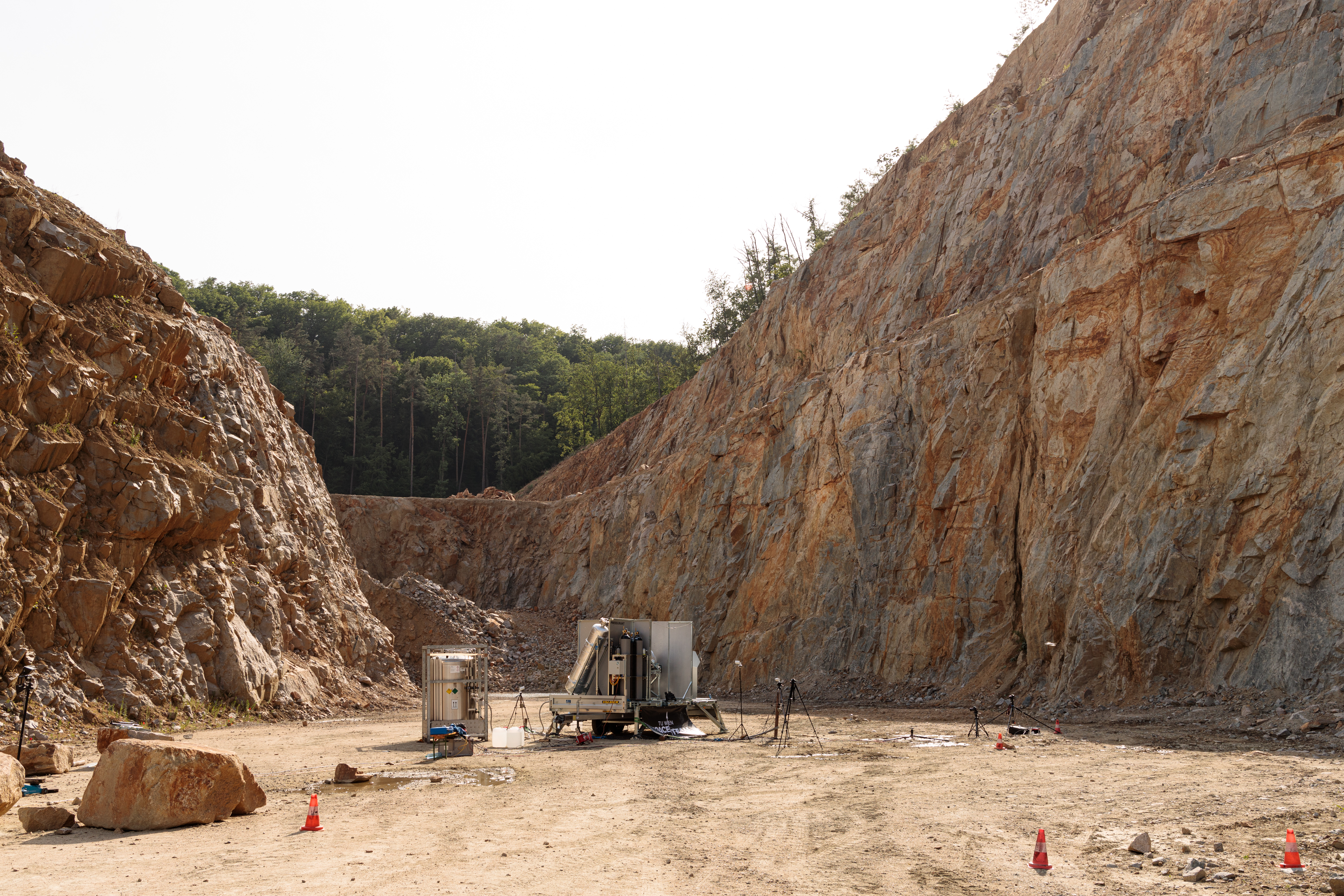
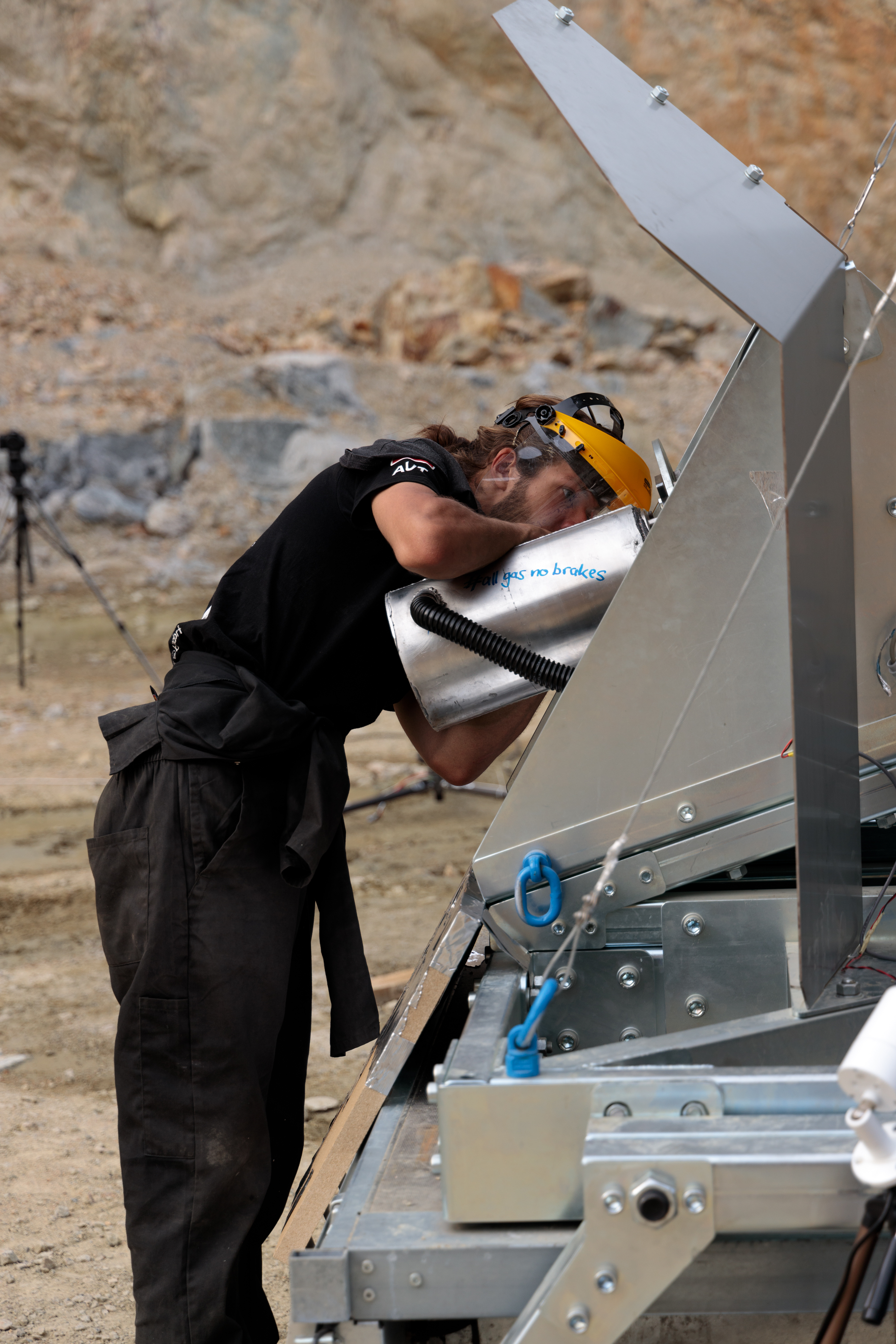
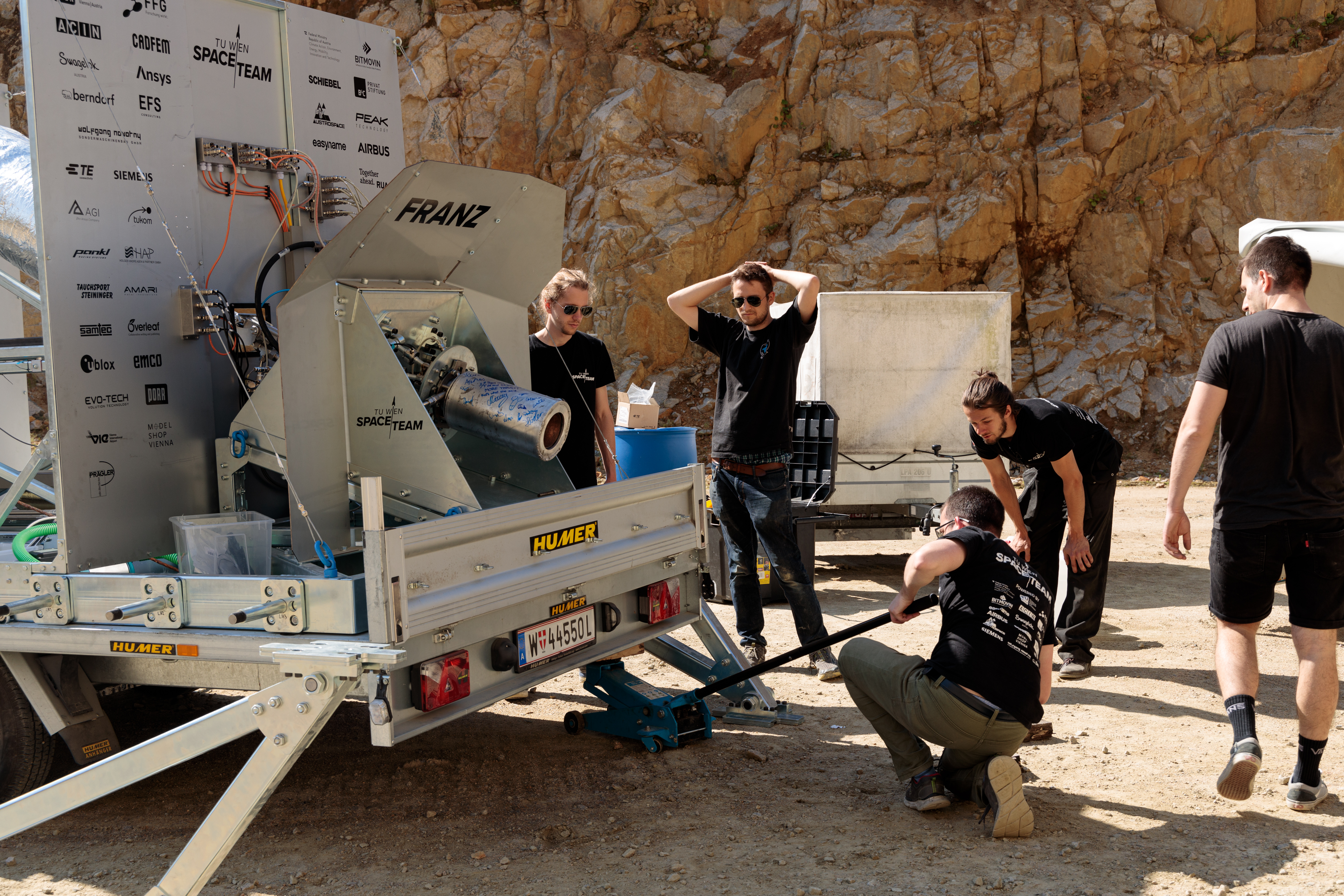
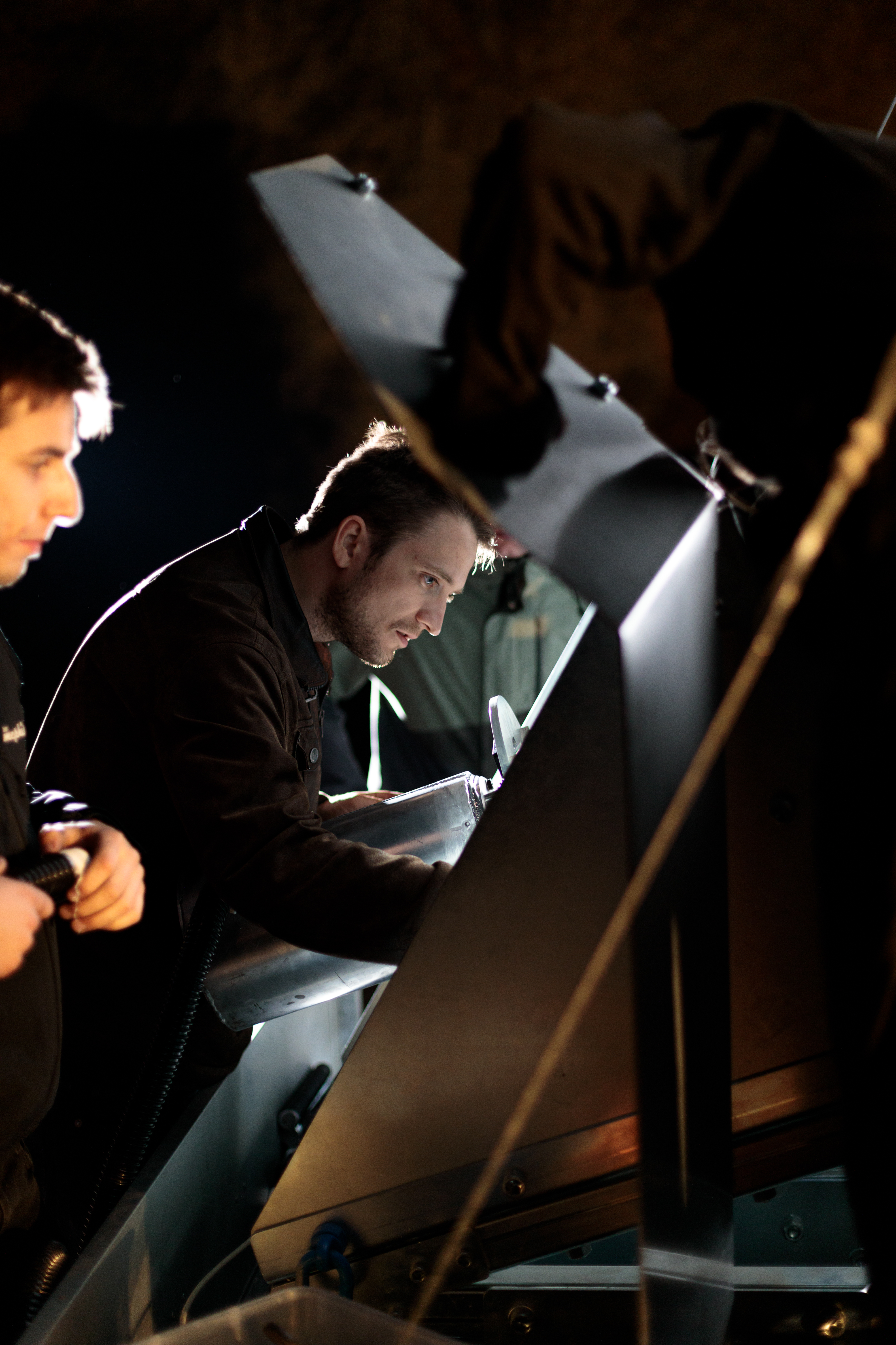
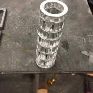
The Green Adjustable Testbed Engine (GATE) is the first iteration of a heavy duty liquid fueled rocket engine design. Based on knowledge gained while developing systems and prototypes for µHoubolt we are now designing our very first adjustable-thrust liquid rocket engine on the largest scale we have operated yet. The test stand TS03-24kN “Franz” is an integral part of the development process to allow us to test GATE’s 8kN of thrust achieved by the two propellants ethanol and liquid oxygen.
TS-03-24kN “Franz”
TS03-24kN “Franz”
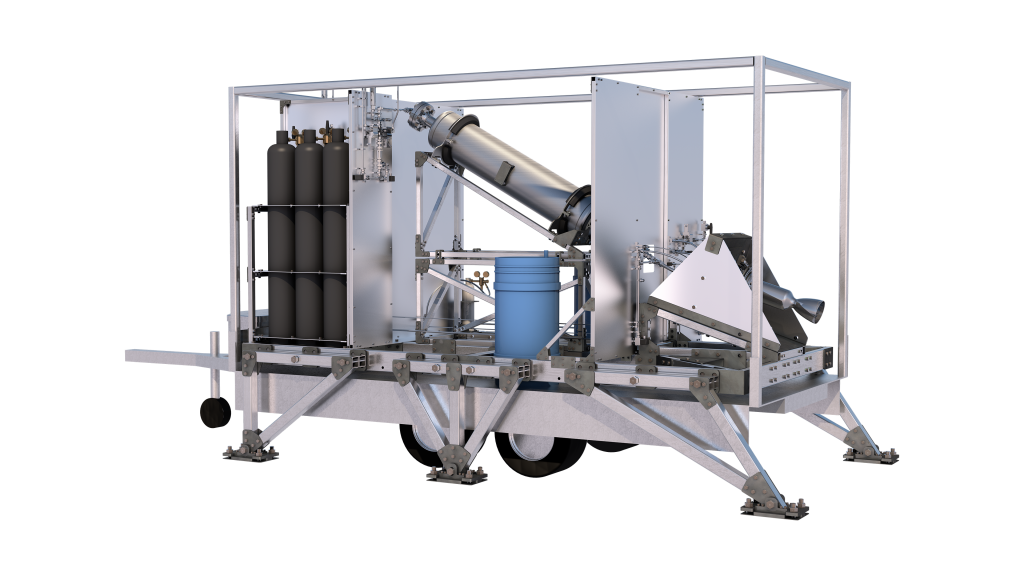
For development of engines of the size necessary for the suborbital rocket Houbolt, a larger test stand has been designed and built. To have abundant capacities for future projects, the test stand is constructed to handle a thrust of up to 24kN, which makes it the largest of its kind ever to be used in Austria. For maximum flexibility it can not only be operated with the propellant combination Ethanol/Nitrous Oxide which is planned for the Houbolt rocket, but also with any other usual combination like e.g. Ethanol/LOX. For more flexibility regarding the test location, the frame is mounted on a trailer which enables repair and maintenance work to be done at the workshop and reduces the requirement for the test location immensely.
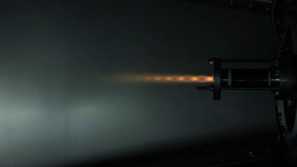
At the start of June a Hot Fire test using the GATE engine was conducted on the test stand – with great success:

System
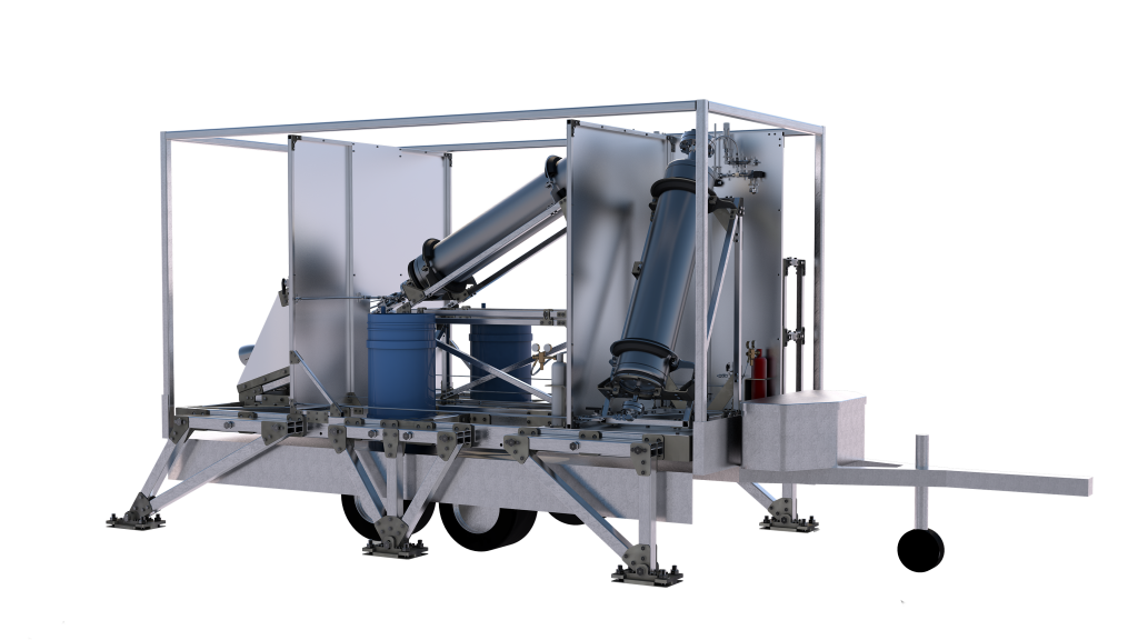
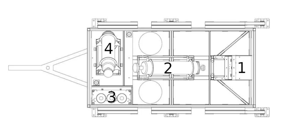
The test stand consists of four main sections, which are separated from one another by steel walls. This sectioning protects against the spread of escaping fluids and fires, any heat radiation in the event of a fire, and flying debris.
In the front section (section 1) you will find the test compartment and any dangerous substances / systems (batteries for pump tests, gas bottles for the torch igniter). The test compartment and thus the engine are angled downward at an angle of approximately 30° in order to ensure that any expelled fuel flows away and does not collect inside the engine in the event of a misfire.
The middle section (section 2) houses the oxidizer tank. It is arranged in an angled position on an elevated scaffold to ensure the shortest possible flow path without any significant pipe bends. This is particularly important to avoid cavitation (pressure fluctuations when flowing around the bend, which sometimes lead to evaporation and subsequent collapse of the liquid). In operation, the tank is mounted on four load cells, which continuously measure the tank mass and thus the mass flow into the engine. In addition, this section has space for two 200l barrels of water whose content is fed to the fire extinguishing system via submersible pumps if required.
Sections 3 and 4 can be found in the rear part of the test stand, section 4 contains the fuel tank, section 3 houses three 50l nitrogen bottles for pressurization of the propellant tanks and for supplying the nitrogen/water mist and purge systems. In addition, there are valve and switch panels for the compressed gas supply as well as the electronics and control system.
Structure
In order to handle the occurring loads, the test stand needs a stable framework, that consists of steel shaped tubes, that are bolted together using connectors. This method leads to a reduced weight, good strength and low costs. So that the trailer is not overstressed, the test stand is able to support itself by anchoring six support pillars to the ground that are capable of handling the entire load during testing. If necessary the trailer can be detached from the test stand and removed from the test site.
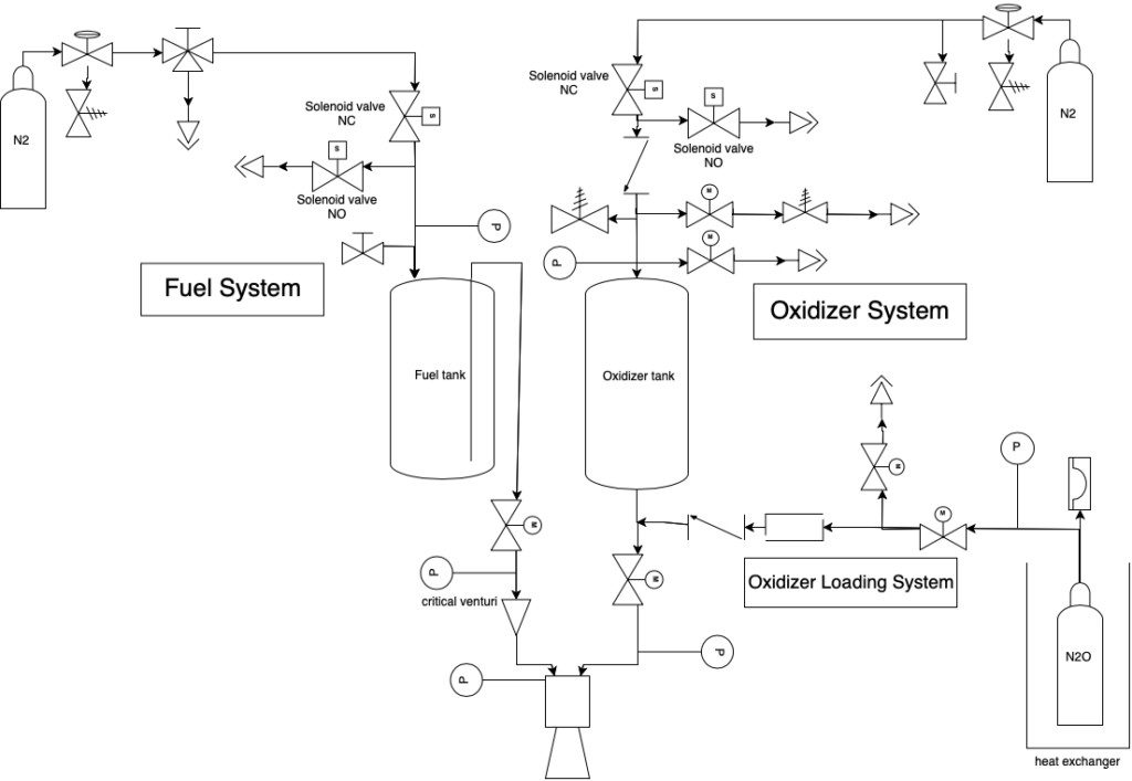
Tanks
The tanks for fuel and oxidizer consist of stainless steel and have their connections at the top and the bottom. The connections at the bottom serve for fueling and unfueling. The top contains the necessary connections for the safety valves and pressure gas supply.
Piping System
The piping system mainly consists of components from Swagelok. These are characterized by high tightness, compatibility and good pressure resistance. The design and composition of the system was also supported by Swagelok.
An electrical system is largely used to actuate the valves; a separate servo attachment for commercial valves was developed for this. A pneumatic system is under development for the two relatively large main valves. The electrical actuators have been in testing for a long time and have proven to be reliable when used on the existing small test stand.
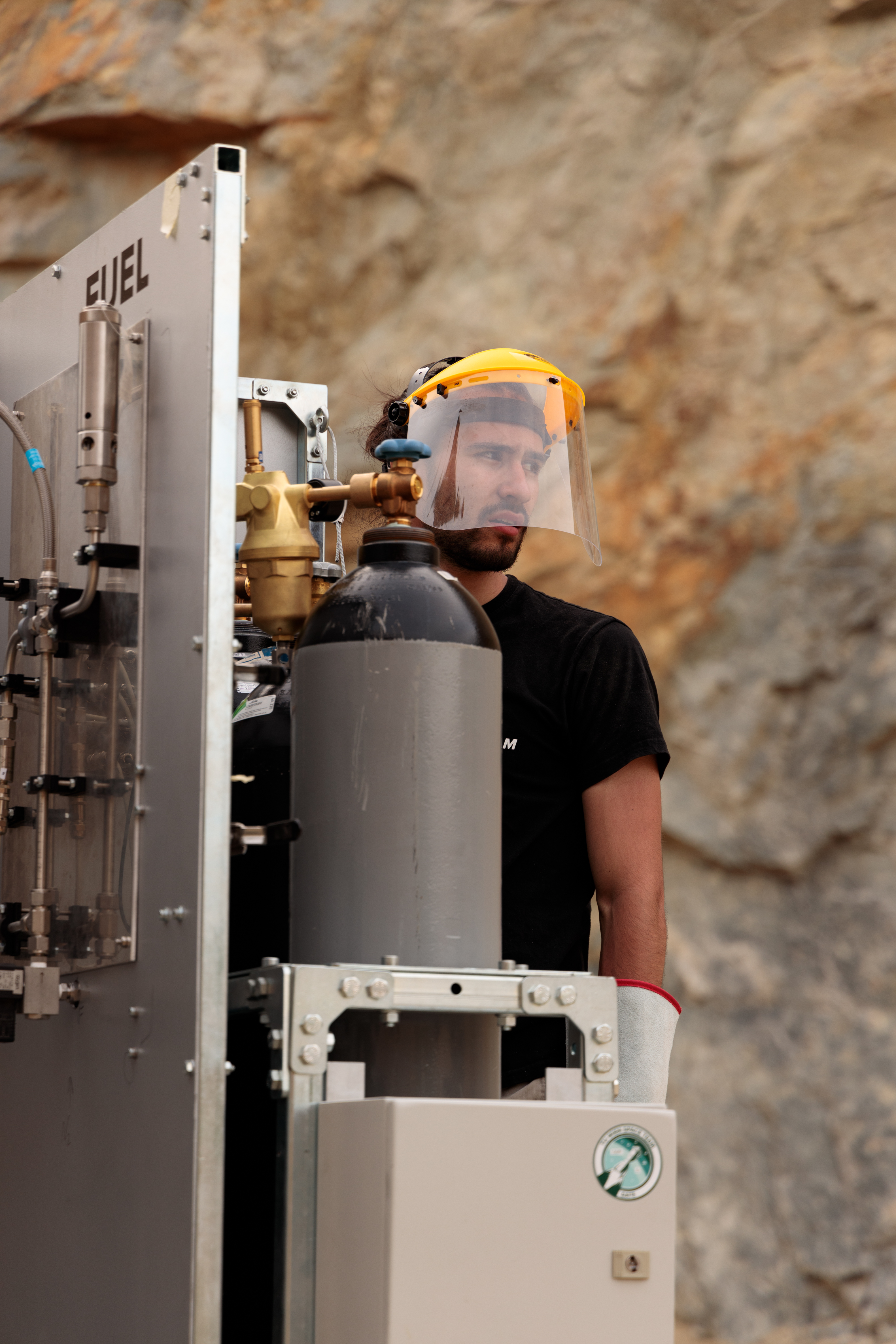
In order to verify the modeling and design of the oxidizer system, the corresponding components have already been procured and are currently being integrated into the existing small test stand. To ensure reliable ignition, a so-called torch igniter (basically a small, easy-to-ignite engine that fires into the combustion chamber of the main engine), which is operated with hydrogen and oxygen, is installed. If necessary, the oxidizer system can be converted from nitrous oxide to liquid oxygen by making minor adjustments to the main valve to support future projects.
Electronics
A further development of the system currently used on the small test stand is used as the control unit for the test stand. This system is able to automatically control the entire test sequence from refueling and valve control to the recording of high-resolution measurement data. The system is adapted for the use of nitrous oxide, in addition an independent watchdog system is used, which monitors the functionality of the main system and offers additional functions to control the oxidizer tank (emergency ventilation, pressure monitoring).
Safety
When developing the test stand, great attention was paid to safety. There has been an extensive safety analysis of the system, especially in relation to the involved substances and pressure-carrying systems. The oxidizer (nitrous oxide) in particular requires some measures to prevent decomposition reactions. Despite all of these measures, all processes that encurage such a reaction (refueling, test runs, ventilation) are carried out automatically or remotely controlled without the presence of personnel. For pressure-bearing systems, only tested and approved components are used and all pressure vessels are equipped with safety systems. Spatial separation and shielding of the individual subsystems as well as an extinguishing system are intended to contain or prevent fires.
TS-02-500N
TS02-500N
The new test stand is a progression from TS01-70N and was designed to carry out engine tests using nitrous oxide as the oxidizer. It differs from its predecessor mainly by the more robust structure and fluid management system. Thus, this test stand allows us to test and develop flight worthy liquid-fuelled engines that can be used in small rockets like µHoubolt. The key data of the test stand are briefly summarized below.
Key data:
- Arrangement – This is again a test stand with a vertical engine arrangement. These designs have the advantage over horizontal arrangements that no fuel can accumulate in the combustion chamber. This reduces the likelihood of a “hard start”, which can damage the engine or the test stand itself.
- Structure – The basic structure consists of a four-legged construction made of stainless steel
- Thrust – In the current configuration, the test stand can be used for engines with a thrust of up to 500 N.
- Propellants:
- Fuel: In general (with the exception of methane) all hydrocarbons can be used, the current tests are carried out with ethanol
- Oxidator: The test stand was primarily designed for the use of nitrous oxide
Piping and Components:
- Piping – The piping and all critical components consist of suitable Swagelok products.
- Pressure supply – The nitrogen for the pressurization of the propellants is provided in gas bottles. The pressurization is carried out by controlling two monostable solenoid valves, so that it can be stopped at any time by cutting off the power supply.
- Valve control – The ball valves are controlled by self developed attachments for servo motors.
- Refueling system – The nitrous oxide tank is filled using a specially designed fill system. The control of the temperature and the necessary pressure difference is ensured by means of a heat exchanger.
- Ignition – The ignition is currently pyrotechnic, an electric arc ignition system is also implemented.
- Thrust measurement – The thrust measurement is carried out by three load cells arranged in a circle so that not only the thrust but also a potential thrust vector offset can be recorded.
A preliminary version of the LE-03 Amalia engine designed for the new test stand has already been successfully tested with ethanol and Nitrox. However, it is currently still under development.
TS-01-70N
TS01-70N
TS01-70N is the first test stand built by the TU Wien Space Team to facilitate the development of small scale prototype rocket engines. The project has introduced a new era of liquid rocket engine development for Space Team and thanks to the now available test platform it was possible to take our first steps in the area of liquid rocket engines with the engines “Thor” and “Proteus”. Thor was designed to use compressed air as oxidator and ethanol as fuel, as it was a cheap, safe and easy to handle fuel mixture – it also wasn’t the most efficient, but for the first tests it was perfect. With Proteus we started switching to NitrOx, which is compressed air that is saturated with oxygen which increases the performance of the engine and brings it more in line with our goal of using nitrous oxide as oxidator. Due to the limitations of the test stand both Thor and Proteus had a maximum thrust of 70N, which is far too low to launch a rocket, but is enough to demonstrate that Space Team is able to design, build and even more importantly, safely operate machines of this complexity without outside support. In 2019 the test stand was decommissioned and replaced by the TS02-500N.
milestones
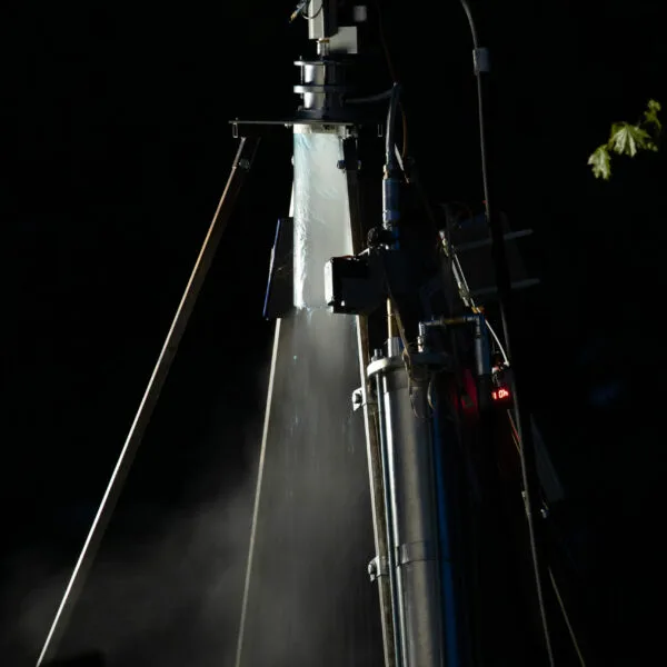
December 2017: The “propulsion working group” conducts the first test series on fuel atomization.
March 2018: After three months of building the LE-01 Thor engine, the first cold flow test (without ignition) is carried out. For safety reasons, a water / compressed air mixture is used first. With the help of a transparent back pressure chamber, the flow behavior can be observed and documented under realistic conditions.
April 2018: The first hot fire test with ethanol / compressed air is carried out. Then compressed air is replaced by the more oxidizing NitrOx.
March 2019: The new LE-02 Proteus engine is put into service. Due to its modular design, the engine is primarily intended to test various combustion chamber and injector designs.
In the further course of 2019 the test stand was upgraded in many ways; the sensor system was improved and a capability for thrust vector measurement was integrated. The latter was implemented using three load cells on which the engine is suspended and which record the forces that occur during the test. In addition, three piezoelectric pressure sensors were installed, which measure the fuel, oxidizer and combustion chamber pressures. With this equipment, the Space Team achieved the first stable combustion in late summer 2019.
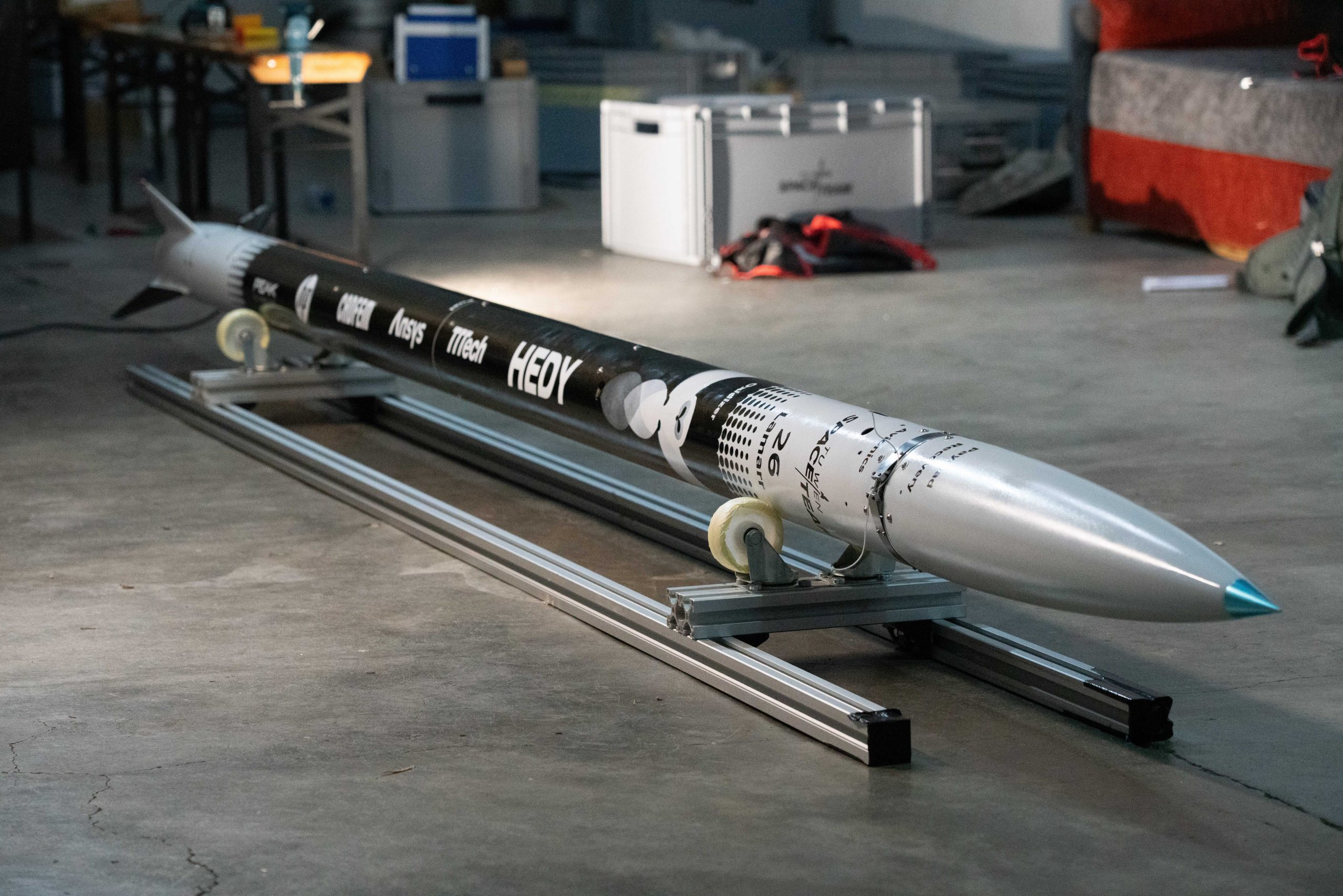
µHoubolt

Micro-houbolt
Mission objective and requirements
The mission goal is to build and launch a liquid fuelled rocket designed to be as simple as possible. Due to the Houbolt concept, the following requirements must be met:
- Flight altitude 3 km
- 1kg payload
- Successful recovery with redundant two-stage parachute system
key data on the micro-Houbolt Mission
| length | 200 | cm |
| mass | 12.1 | kg |
| payload capacity | 1 | kg |
| thrust | 600 | N |
| apogee | 3 | km |
| Max. speed | 225 | m/s |
| Max. acceleration | 4.6 | g |
Airframe
The airframe was designed to first of all be as lightweight as possible to help with a sufficiently high rail exit velocity and secondly to be as simple as possible to not complicate the launch preparation procedure. This ensures that we can focus on the preparation of the more complex propulsion section.
The nose cones core is 3D-printed with PVA, a water-soluble filament. After laminating it with glass fiber reinforced plastic, the core gets removed by dissolving it in water. Small scale tests appear to be promising.
We plan to mould the fincan with the help of our sponsor Peak Technology, similar to STR-03. A detailed description of the procedure can be found here.
The carbon fiber reinforced plastic main tube has a diameter of 123 mm and cutouts for refueling the tanks. Rail buttons guide µHoubolt along the launch rail.
Recovery System
µHoubolt uses a clamp band for recovery. Twelve v-clamps are bolted to a metal band. The ends are joined together with a piece of string to hold the nose cone and the body tube together. The clamp band is tightened with a tangential screw. At apogee, a CYPRES line cutter cuts the string to allow the metal band to relax and the nose cone to separate. The two coupler parts and the clamp band are machined in house. We have already proven the idea to work by using a prototype of the clamp band in our experimental rocket STR-10 Leonor.
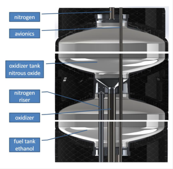
Propellant Tanks
The vehicle has two separate propellant tanks for the oxidizer (nitrous oxide) and the fuel (ethanol). The nitrous oxide tank has a volume of 2300 ml, a working pressure of 40 bar and an empty weight of 1200g, while the ethanol tank has a volume of 860 ml, a working pressure of 30 bar and an empty weight of 680 g. With nitrous oxide tanks in particular, care must be taken to ensure that all materials are compatible with the medium to be stored.
Due to issues in sourcing nitrous oxide and the inherent risk of thermal decomposition of nitrous oxide we conducted tests at cryogenic temperatures to evaluate the use of liquid oxygen (LOX) as oxidizer instead. The first version of µHoubolt will not fly with LOX, as the design is already too mature for such a change. However we intend to use LOX in the next iteration of µHoubolt.
Pressurization System
The propellants are fed from the propellant tanks into the combustion chamber by means of pressurization with nitrogen. The nitrogen is stored in high pressure vessels and regulated to the required working pressure of the tanks. This method represents a less complex option in comparison to other feed methods. In rockets as small as µHoubolt, it has the additional advantage that the increased mass of the more robust propellant tanks is far outweighed by the absence of other components like pumps, a gas generator, electric motors / battery, etc.
For µHoubolt, paintball pressure components will be used as 300 bar pressure tanks. The associated equipment (pressure regulators, fill equipment, …) is available in great variety commercially, which reduces design time, costs and ensures a certain level of safety.
As these parts have not been made for use in rocketry and no detailed performance data is available, it first had to be evaluated if the components are able to supply the necessary pressure as well as mass flow rate. These tests have been successful, meaning these commercial off the shelf components are viable for use in µHoubolt.
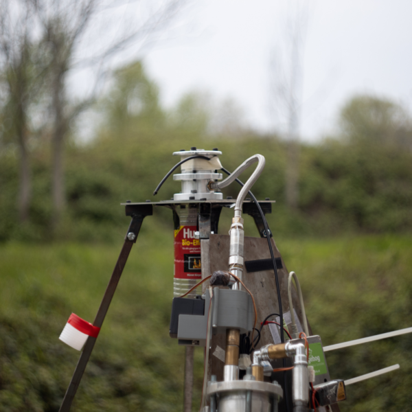
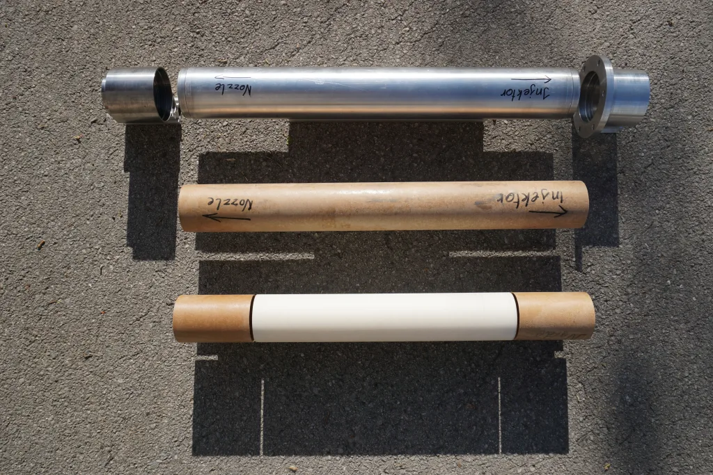
engine
The heart of the vehicle is our in-house developed and manufactured liquid rocket engine. As this is the first engine of its kind in use by the TU Wien Space Team, a lot of validation and testing has to be done to ensure smooth operation for the actual launch of the rocket – to facilitate this, the test stand TS02-500N has been developed and manufactured by the team.
Injector & Valves
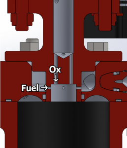
µHoubolt is powered by the engine “Amalia”, with a thrust of approximately 500N. The oxidizer is fed into the center of the engine from above and passes through orifices that are used to regulate the mass flow and decouples it from the pressure in the combustion chamber. Fuel is fed into the engine from the side through a cavitating venturi, which serves the same purpose. The propellants are then introduced into the combustion chamber through an unlike-doublet impingement injector, where streams of oxidizer impinge with streams of fuel to mix and atomize.
Propellant flow is controlled by two ball valves actuated by electrical servo motors, allowing the startup sequence to be configured precisely in software. The engine also includes redundant internal pyrotechnic ignition charges, avoiding the need for placing igniters through the throat and externally wiring them to the launch pad or rocket.
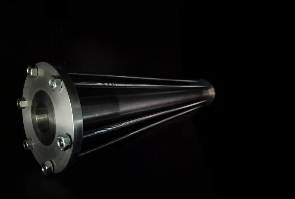
Combustion Chamber
To prevent the combustion chamber walls from overheating and disintegrating from the severe heat of the combustion, a cooling concept is needed. Capacitive, film and ablative cooling was considered. We are currently focusing on ablative cooling as it is simple and has a small mass footprint. Ablative cooling works by coating the inside walls with a heat absorbing material that evaporates while burning, carrying heat away from the combustion chamber walls. An ablative combustion chamber is a consumable built for single use, so it has to be replaced between firings.
Capacitive cooling is even simpler. By having enough heat capacity, the combustion chamber simply withstands the exposed heat without getting too hot. The drawback is that the resulting engine is much heavier, creating problems with aerodynamic stability and reducing the overall rocket performance. Film cooling on the other hand utilizes a film of a fuel-rich mixture close to the combustion chamber walls which evaporates and burns at a lower temperature, essentially shielding the chamber from the intense heat of the main combustion. To implement this, a more complex injection system would be needed, so we prefer the simpler ablative cooling method.
A cooling method that wasn’t considered due to being unsuitable for such a small engine (and difficult to manufacture) is regenerative cooling, where one or both of the propellants flows through cooling channels in the combustion chamber walls before getting injected to be burnt. This method will be considered in the future for larger engines.
Avionics
The avionics of µHoubolt are used to control the vehicle. Data is collected at multiple places in the rocket using a wide variety of sensors and compared with expected values. “Avionics” is the umbrella term, which in our case is divided into five sub modules:
- ECU (Engine Control Unit) – Has a variety of sensors to validate the flight profile and engine characteristics. It is responsible for actuating the valves, activating igniters and to monitor temperatures and pressures.
- PMU (Power Management Unit) – Serves to power most subsystems in the rocket and converts the voltage from the batteries to the necessary voltage levels. It also contains a safety pin which prevents arming and engine ignition until the pin is removed.
- RRU (Redundant Recovery Unit) – The Recovery Unit (RU) is responsible for triggering both recovery events. In case of failure of one RU, the second RU (which is commercial off-the-shelf) will trigger the recovery.
- RCU (Radio Control Unit) – The radio control unit is used to enable communication between the rocket and the ground systems during the flight. Current sensor readings are transmitted dynamically when a favorable signal path is available. Additionally, a GNSS receiver is used to measure the position of the vehicle.
- DLU (Data Logging Unit) – The Data Logging Unit is the equivalent of the flight data recorder or “Black Box” in airplanes. It contains its own set of sensors and a backup battery in a more robust casing to increase the chance of getting uncorrupted flight data in case of a system failure or rough landing. Additionally, the DLU records the communication between the other modules over a CAN bus.
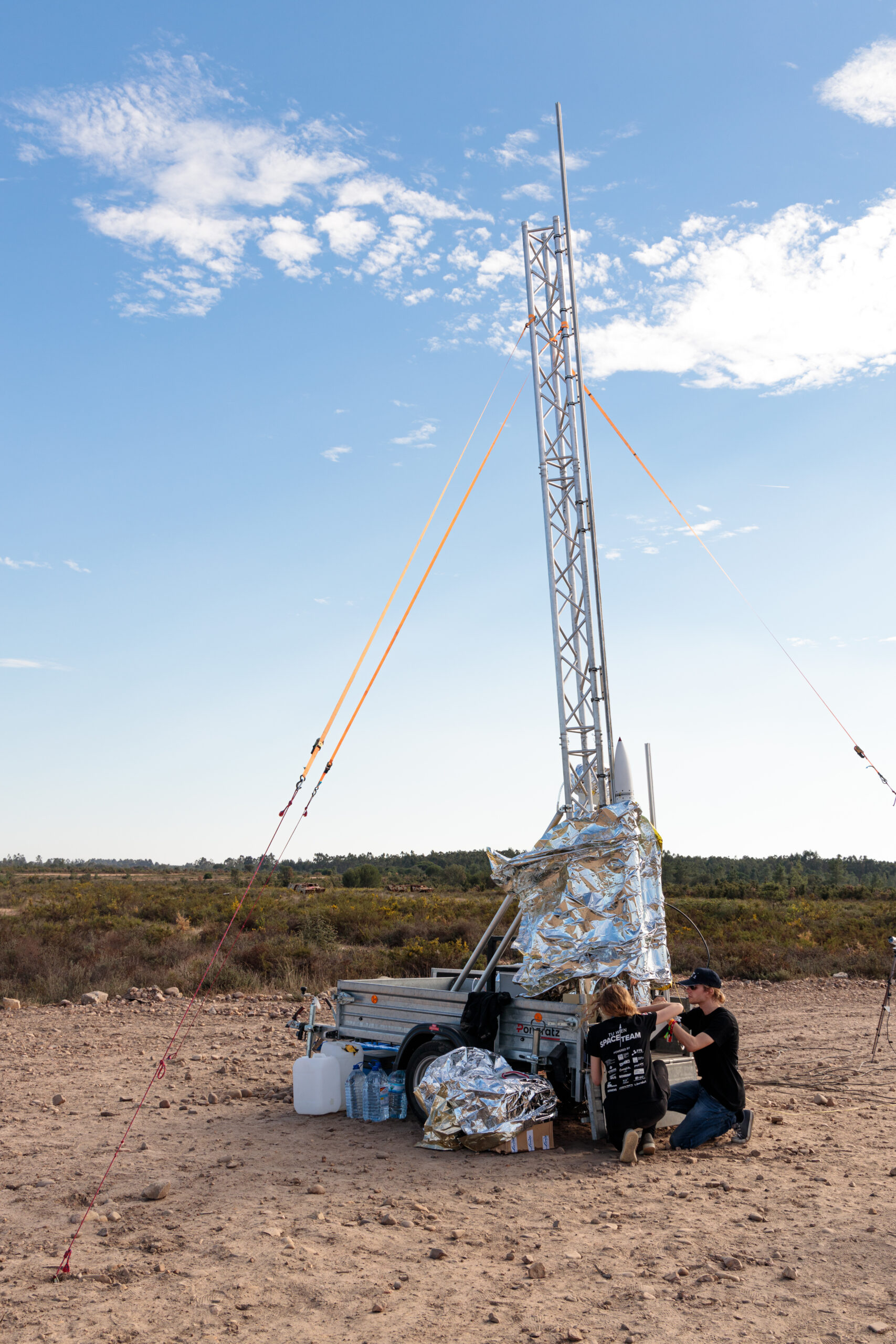
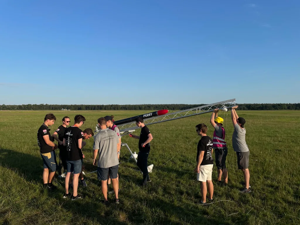
Launch Pad
The launch pad, in addition to its own control system, contains the connections to the rocket (power supply, data bus and filling hoses), which can be automatically disconnected and retracted. The oxidizer and pressurant filling procedures are fully automated to avoid the need for personnel to be present, increasing safety. A hold down system is also integrated in the launch pad, which only releases the rocket if the engine performance after ignition is sufficient for a safe liftoff.
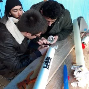
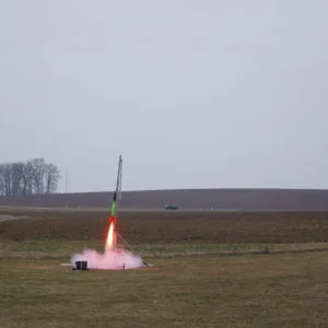
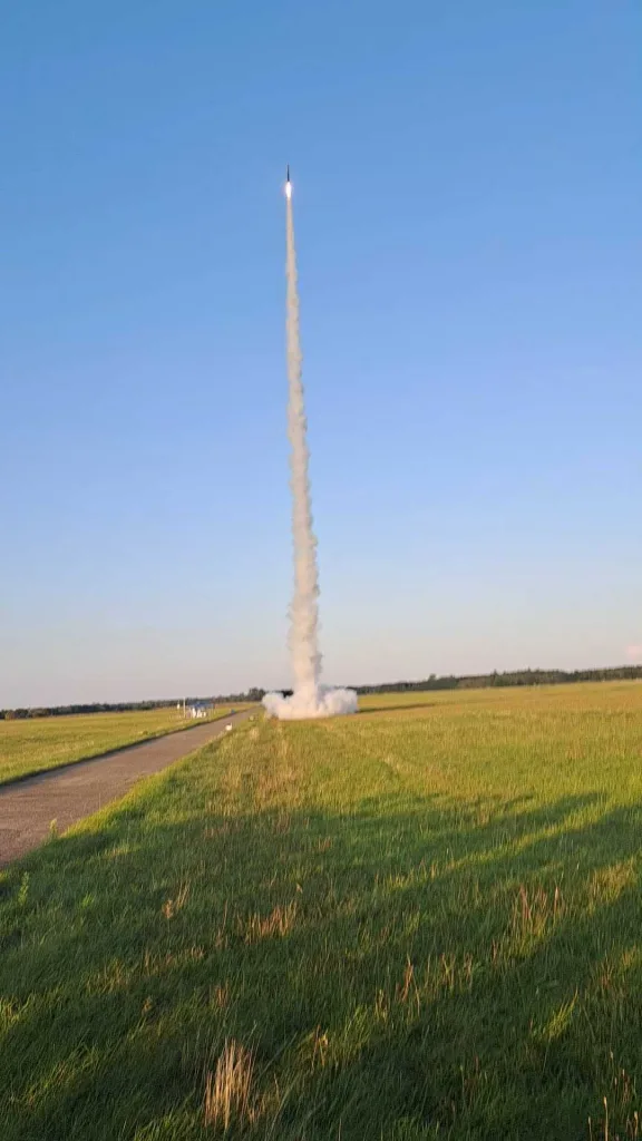
Start in Straubing
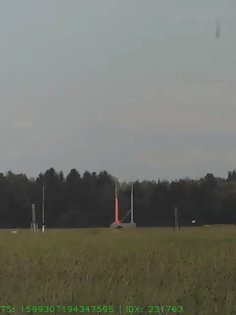
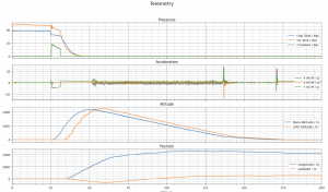
Am 25.Juni erfolgte der Erstflug von µHoubolt in Straubing, Deutschland. Nach der relativ langen Anreise wurden die Startvorbereitungen gegen 14 Uhr begonnen. Die Vorbereitungen der Rakete und Bodensystem verliefen überwiegend problemlos. Innerhalb weniger Stunden war die gesamte Start-Infrastruktur (Startrampe, Betankungsanlage, Mission Control) aufgebaut und einsatzbereit. Da dort die maximale Flughöhe beschränkt ist, verringerten wir die Brenndauer auf 4s, um eine maximale Flughöhe von 1 km zu erreichen. Nach dem erfolgreichen Betanken der Rakete mit sowohl Brennstoff als auch Oxidator war die Rakete bereit ihren Erstflug anzutreten.
Das Zünden des Triebwerks funktionierte einwandfrei. Der Hold Down Mechanismus wurde ausgelöst und µHoubolt zog in den Himmel. Aufgrund des relativ starken Windes und der niedrigen Startgeschwindigkeit drehte sich die Rakete in den Wind. Dies führte zu einer hohen Horizontalgeschwindigkeit beim Apogäum, wodurch die Leine zum Vorschirm leider gerissen ist. 250m über dem Boden wurde der Hauptfallschirm ausgeworfen, dieser riss aufgrund der hohen Fallgeschwindigkeit ebenfalls. µHoubolt schlug in den guten bayerischen Boden ein. Trotz der Bruchlandung war der Start ein Erfolg, da das gesamte Antriebssystem vollständig funktioniert hat und nur der Fallschirm Schock stärker war als erwartet. Nichts desto trotz konnten wir aus diesem Fehler lernen und die gewonnenen Informationen für die nächste Iteration von µHoubolt nutzen.
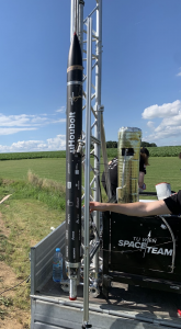
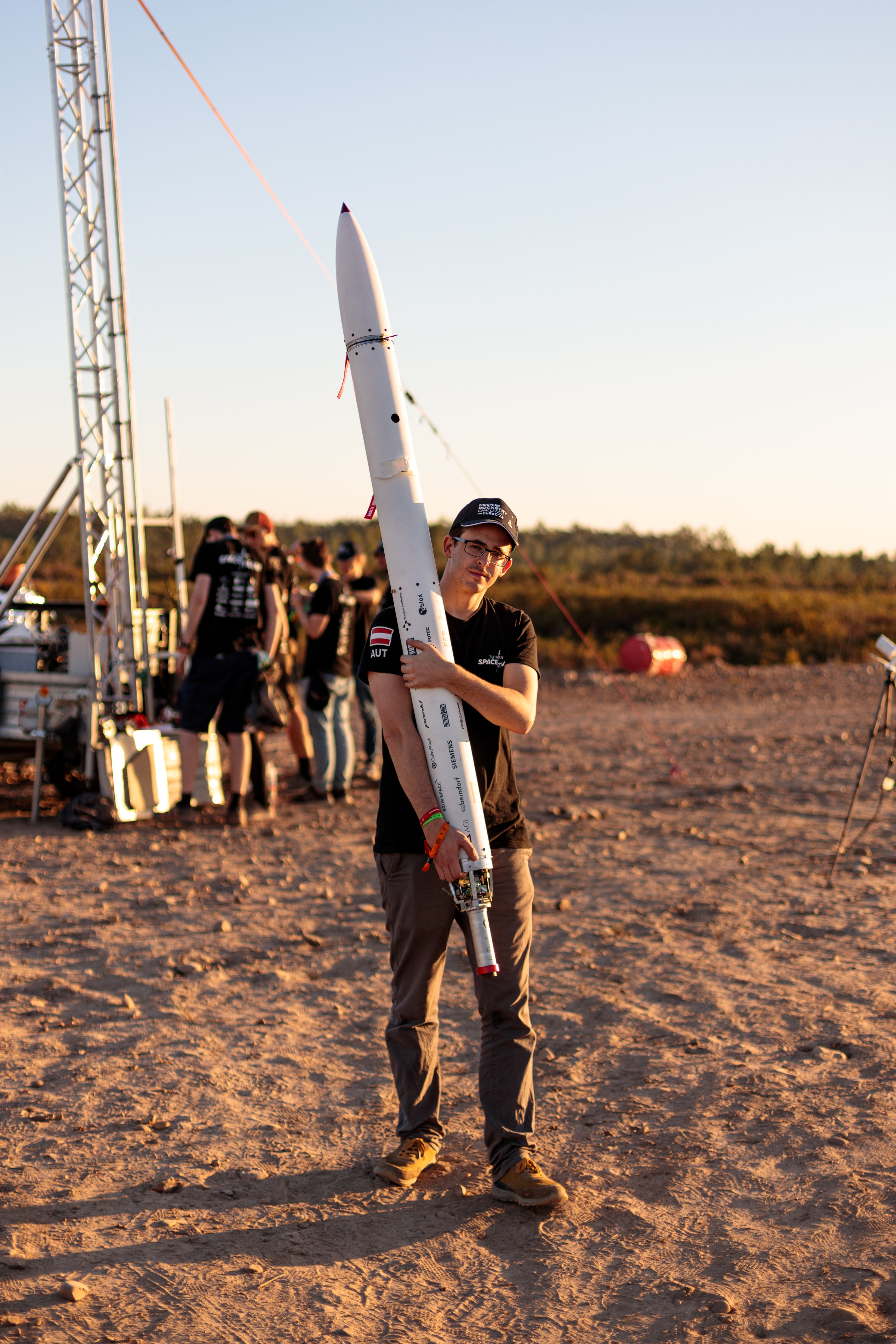
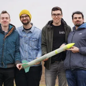
EuRoC 2022
Nach der harten Landung in Straubing standen wir erstmal mit einer bei weitem nicht flugfähigen Rakete da. Unser Ziel an der EuRoC (European Rocketry Challenge) teilzunehmen wollten wir aber immer noch erreichen, also machten wir uns an die Arbeit und fertigten eine neue Rakete. Diesmal mit einigen Verbesserungen, die uns einen erfolgreichen Flug bescheren sollten. Nur wenige Bauteile konnten wiederverwendet und in der zweiten Version verbaut werden, dennoch hatten wir wenige Monate später erneut eine funktionstüchtige Rakete. Bevor wir allerdings tatsächlich teilnehmen konnten, mussten wir einen erfolgreichen Hotfire Test vorweisen. Diesen konnten wir am 30. September durchführen und waren somit startklar für die EuRoC 2022, welche in der Zeit vom 11. bis 18. Oktober stattfand. Einige Teammitglieder machten sich schon drei Tage vor Beginn der Veranstaltung mit dem Auto auf den Weg nach Portugal, um die Launchrail, die Bodensysteme und die Rakete nach Ponte de Sor zu transportieren. Der Rest des Teams reiste am 10. Oktober mit dem Flugzeug an und begann schon kurz nach der Ankunft mit den Vorbereitungen an der Rakete.
Am Tag darauf bauten wir unseren Messestand im Paddock auf. Hier war µHoubolt das Highlight der Ausstellung, da es die einzige Flüssigtreibstoffrakete war.
Den zweiten offiziellen EuRoC-Tag nutzten wir, um die Rakete so herzurichten, dass wir das FRR (Flight-Readiness-Review), welches am nächsten Tag stattfinden sollte, abhalten konnten.
Am 13. Oktober stand das FRR an, bei dem zwei Mitglieder der EuRoC Jury die Rakete genau unter die Lupe nahmen und entschieden, ob die Rakete die Vorgaben erfüllte, um an der Challenge teilzunehmen. Die Jury war beeindruckt von µHoubolt, bat uns aber bis zum Folgetag noch ein paar Dokumente nachzureichen.
Diese reichten wir am Tag darauf nach und konnten somit am nächsten Tag zur Launch Site fahren.
Am 15. Oktober machten wir uns sehr früh auf den Weg zur Launchsite, einer Basis des portugiesischen Militärs. Allerdings hatten wir einige kleinere technische Probleme, die uns leider dazu zwangen, den Start auf den darauf folgenden Tag zu verschieben.
Wir begannen erneut schon sehr früh mit den Vorbereitungen, um gleich im ersten Startfenster zu starten, allerdings spielte das Wetter nicht mit, es fing an zu regnen. Uns blieb nichts anderes übrig, als zu hoffen, dass sich das Wetter bis zum nächsten Startfenster bessert. Kurz vor 14 Uhr erhielten wir die Nachricht, dass wir im nächsten Zeitfenster starten können und begannen nun mit dem Betanken und den finalen Vorbereitungen.
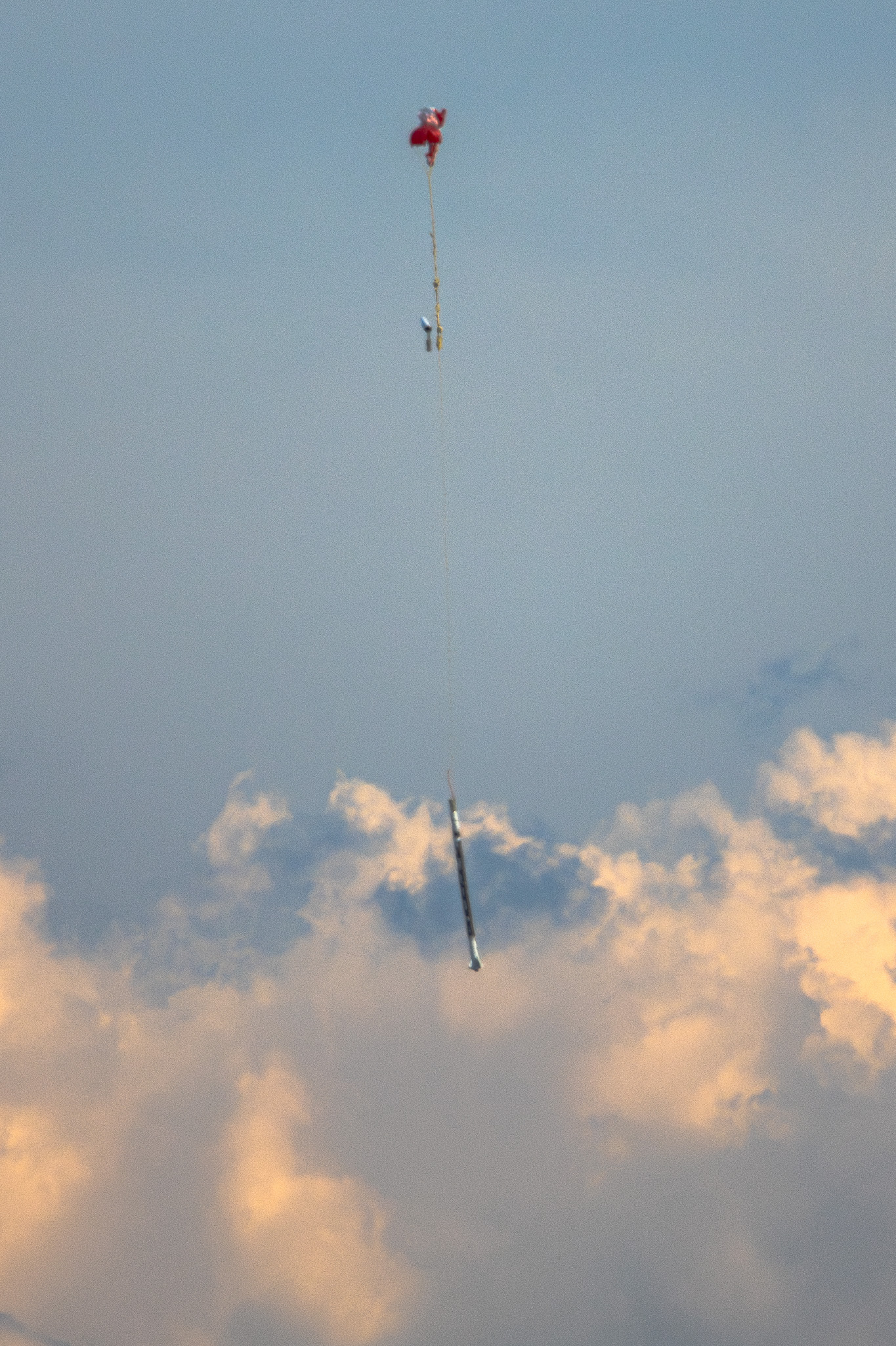
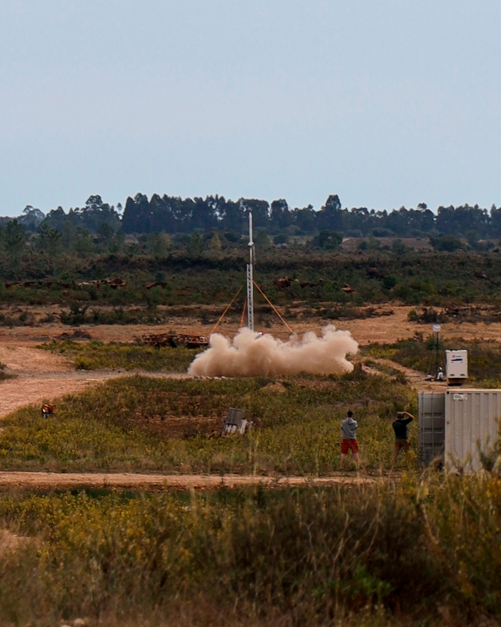
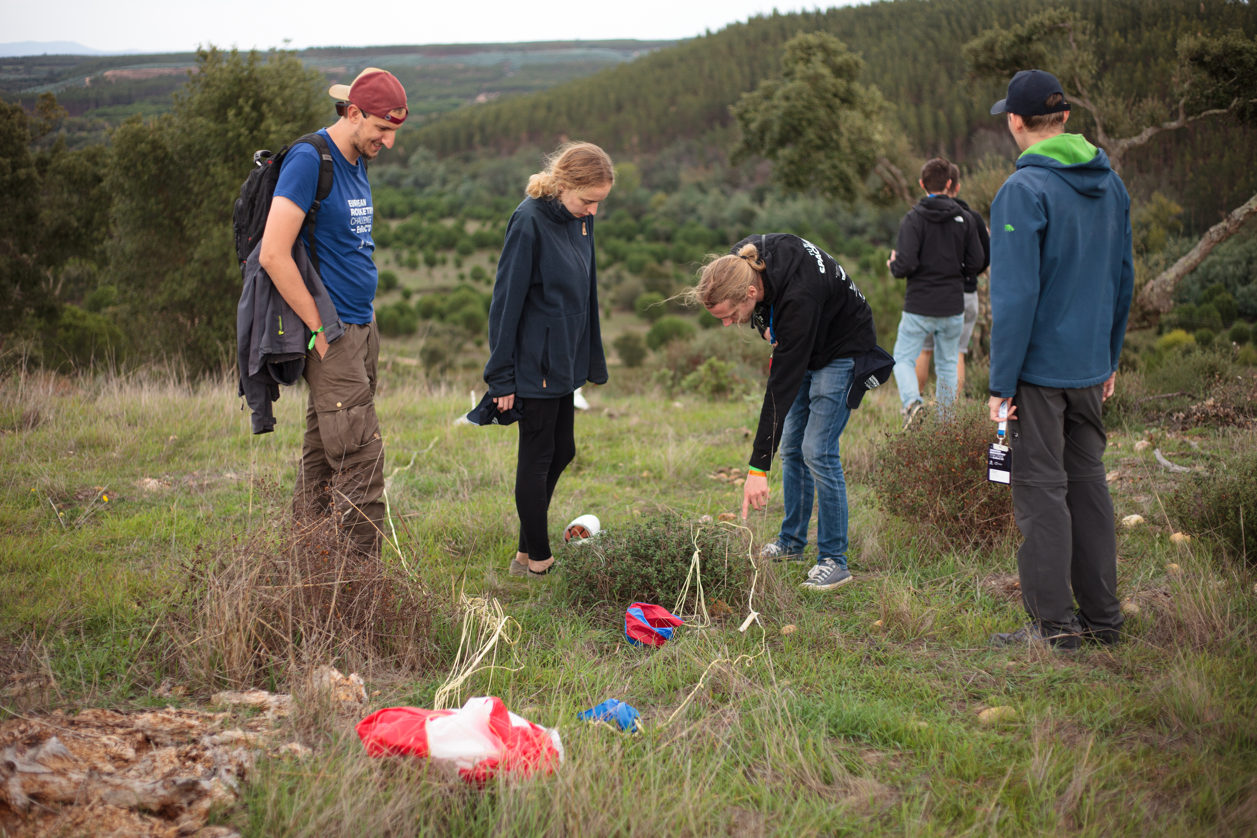
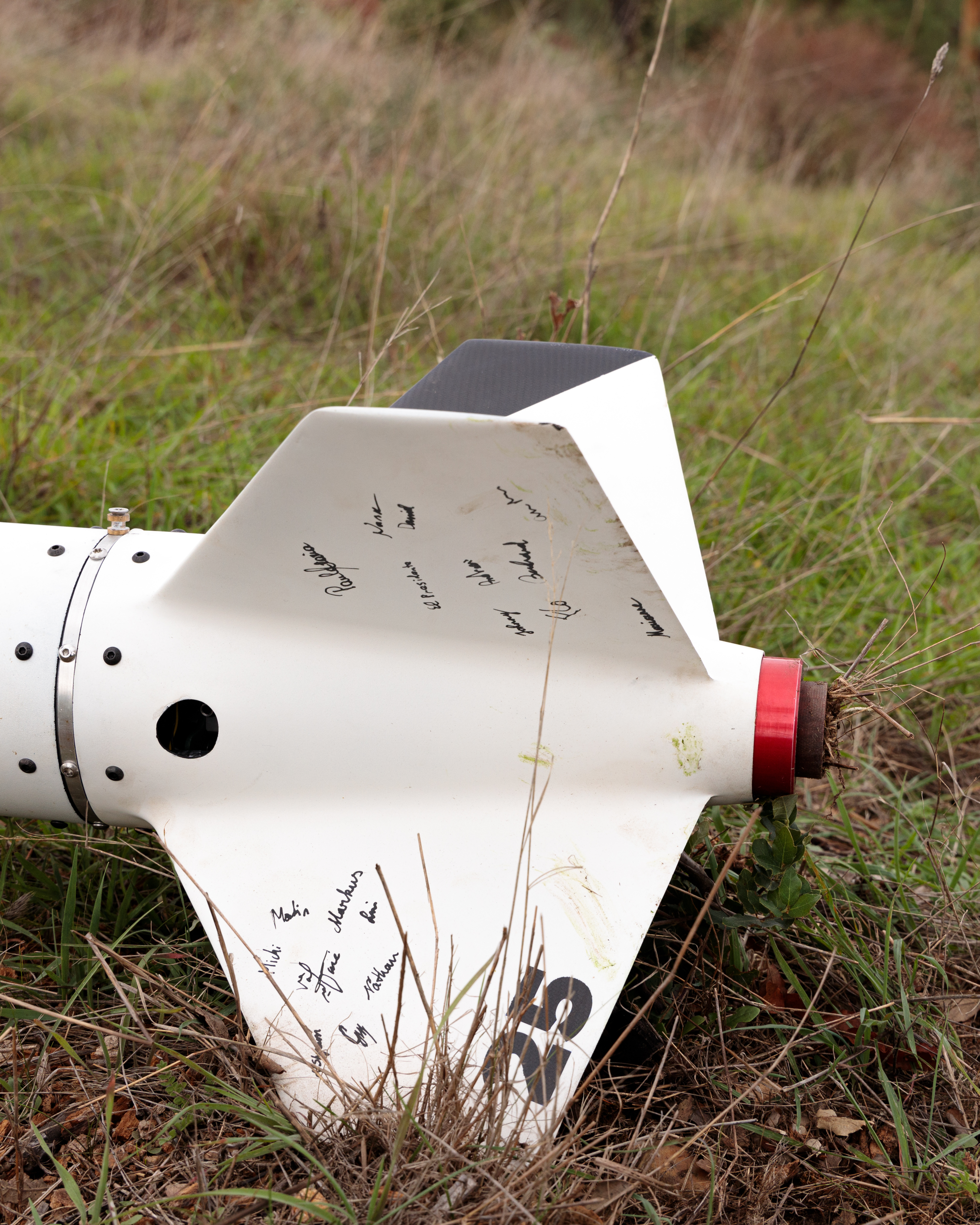
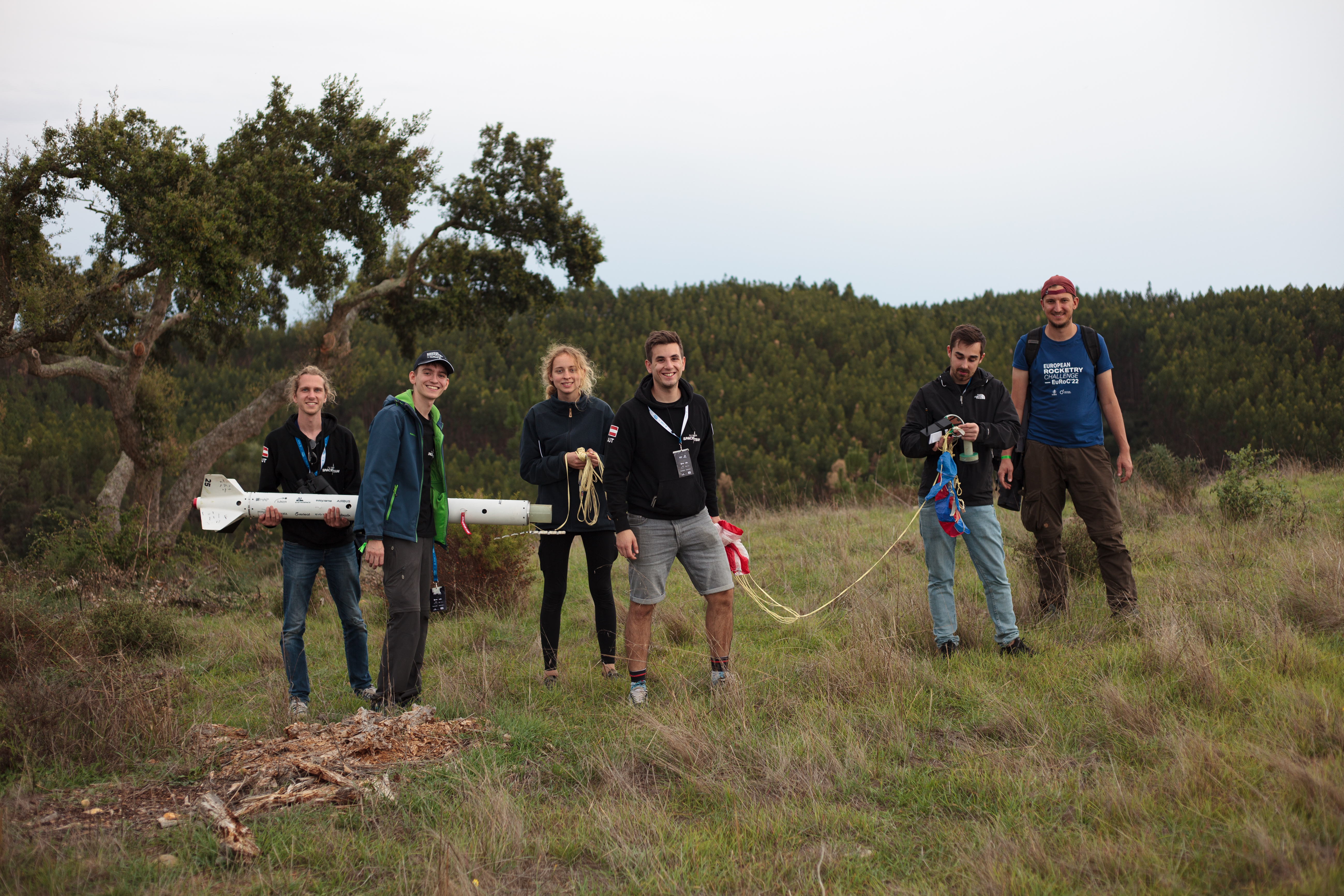
Um 14:11 war es dann soweit, wir bekamen die Freigabe zu starten, koppelten unsere Betankung ab und starteten unseren Countdown. Die Rakete zündete nominal und begann ihren Aufstieg in den Wolken bedeckten Himmel auf ungefähr 2,2 Kilometer Höhe. Hinter der Wolkendecke, am Apogäum, löste der Flugcomputer das Bergungssystem aus und warf den Drogue Fallschirm aus. In einer Flughöhe von 250 Metern wurde der Hauptfallschirm ausgeworfen und die Rakete landete sanft auf einem kleinen Hügel in etwa 1,6 Kilometern Entfernung. Die Rakete sendete uns bis kurz vor der Landung durchgängig ihre GPS-Position, doch die Bergung wurde uns weiter erleichtert, da einer der vielen im Gebiet positionierten Feuerwehrmänner unsere Rakete beim Sinken beobachten konnte und genau sah, wo sie landete. Wir wurden von einem LKW des portugiesischen Militär abgeholt und konnten die Rakete in nur 20 Minuten zurück zur Launchsite bringen. Die Rakete war praktisch unversehrt, was uns auch die volle Punktzahl für das Recovery Scoring der Challenge brachte.
Mit unserer Teilnahme an der diesjährigen European Rocketry Challenge konnten wir den ersten erfolgreichen europäischen Flüssigraketen-Start eines Studierendenteams mit vollkommen gelungener Bergung durchführen. Dieser Erfolg wurde von Seiten der EuRoC mit dem Flight Award der Flüssigantrieb-3km-Klasse ausgezeichnet.
Sowohl alle anderen Teams, als auch Vertreter der Luft- und Raumfahrtindustrie zeigten großes Interesse, da wir nicht nur durch das deutlich komplexere Antriebssystem herausgestochen sind, sondern gleichzeitig auch zu den kleinsten Raketen gezählt haben.
Abschließend ist zu sagen, dass wir sehr Stolz auf diesen Erfolg sind und das Missionsziel für µHoubolt zur Gänze erfüllt haben.
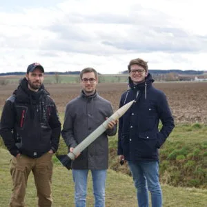
Houbolt (concept)
Houbolt (concept)
Houbolt is our long term vision for the future, it is a liquid fueled rocket that reaches space. In the past, we pursued this vision as part of the Base11 Space Challenge, meanwhile we are going our own way and are working on our first liquid fueled rocket µHoubolt. Once µHoubolt and its successors had their first successful flights, we will pick up where we have left off and revive the Houbolt project.
The Houbolt rocket concept originated from the long term goal to develop and manufacture a liquid fuel rocket engine and the accompanying technology. Creating such an engine technology from scratch is no small feat and has brought a number of sub-projects to life developing sub-assemblies, small scale models and prototypes. To be able to validate behavior and test everything from different part geometries, various igniter mixtures, checklists, Firm- and Software with faster iteration times and lower cost, project µHoubolt has been started as a preliminary, smaller scale rocket. To build, test and validate the engines that go into either of these rockets, the test stands TS02-500N and TS03-24kN have been built.
Base11 Space Challenge
The Base11 Space Challenge is a North American competition for student teams whose goal is to get students interested in aerospace and to promote new talent in this field. In order to win the competition, teams have to build a single stage liquid fuelled rocket and fly it successfully into space, i.e. to at least 100 km altitude as the first of 33 teams and before the end of 2021. The winning team wins a prize money of $1million. In addition, there is also prize money for several intermediate goals.
Spaceport Toronto X Vienna
Participation in the Base11 Space Challenge is reserved for teams from the US and Canada. That’s why we teamed up with the University of Toronto Aerospace Team (UTAT) and took part in the challenge under the common team name Spaceport Toronto X Vienna, TXV for short. Together we wanted to win the competition and create the starting point for a transatlantic student network.
The collaboration between the teams was going well as we complement each other perfectly. The areas of expertise of the two teams differ, so the systems could be easily divided. Together, we could draw on a wide range of know-how, which is definitely needed to realize such a large project. Most of the collaboration was done via the Internet, but we were also able to get to know our Canadian colleagues personally during a safety meeting in Toronto and a hot fire demonstration in Texas. In the meantime the collaboration was reduced to occasional exchange of knowledge as we no longer participate in the Base11 Space Challenge, though we still pursue the vision of reaching space with a liquid fueled rocket.
Houbolt
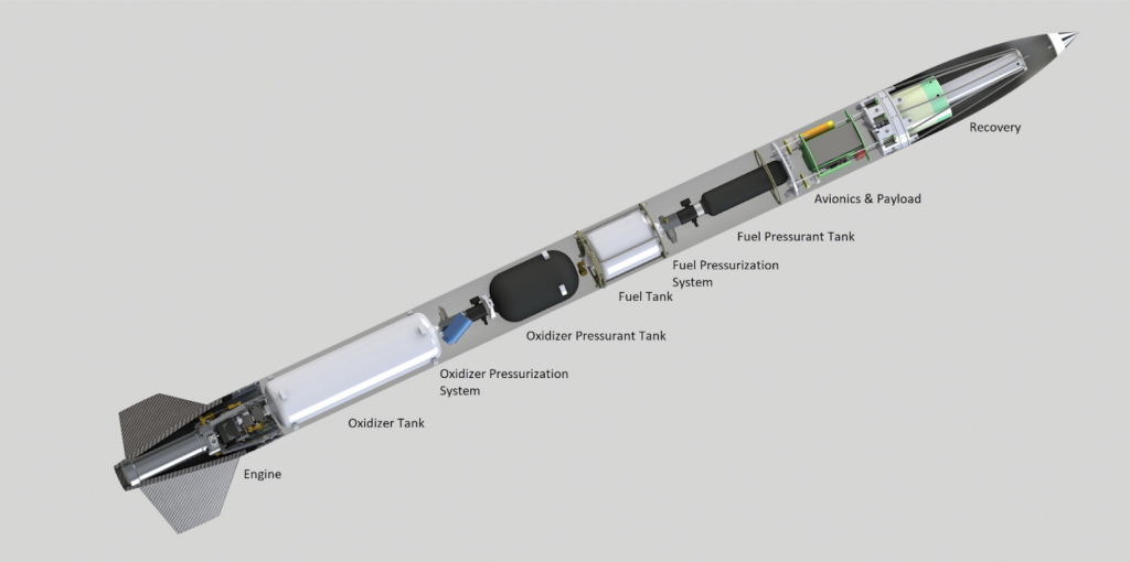
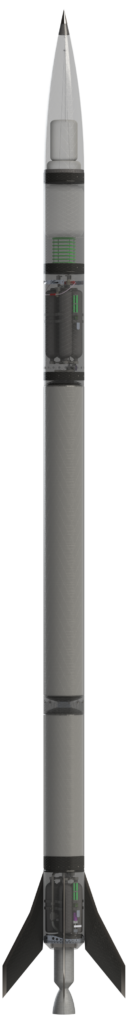
Every space mission requires a suitable launch vehicle. Our rocket Houbolt, named after NASA engineer John C. Houbolt, is the ideal combination of simple design and innovative technology. We rely heavily on lightweight composite materials that allow us a comparatively small and therefore safer design. The requirements for a highly efficient and complex rocket engine are also relaxed. This leads to simplification of the technology and subsequently to a reduction of cost and development time. With a dry mass of only 125kg (410kg fueled) and a length of 8.5m and a diameter of 30cm, our vehicle is small and light in terms of the intended mission profile. The propellants used are ethanol and liquefied nitrous oxide, whose combustion propels the rocket with a thrust of 8.5 kN.
As the first interim target of the Base11 Challenge, a Preliminary Design Report (PDR) was written until March 2019, which among other things contains a detailed description of the rocket and its subsystems. These are briefly explained below.
Design of Houbolt
Recovery Bay
The Recovery Bay includes a two-stage recovery system that allows a soft landing and makes the rocket fully reusable. The internally developed spring-ring separation system promises reliable operation, both in the atmosphere and in vacuum.
Payload Bay
The payload bay can hold up to 5 kg of scientific payload and provides power and mounting points for experiments in weightlessness.
Upper Engineering Bay
The Upper Engineering Bay contains nitrogen pressure tanks for oxidizer pressurization and avionics. A cold gas thruster system for controlling the roll rate is also fed from the composite pressure tanks and is also housed in this section.
Propellant Tanks
The use of Type IV carbon fiber composite tanks allows a very light construction. In addition, the carbon fiber reinforced structure of the tanks is able to completely replace any additional outer shell. The tanks are arranged in a tandem arrangement.
Lower Engineering Bay
The Lower Engineering Bay contains nitrogen pressure tanks for fuel pressurization, main valves, connections to ground systems, an engine gimbal and avionics.
Subsystems of Houbolt
Recovery
The main parachute is a round cap parachute with a hole in the center. This type has a high drag coefficient which allows us to use the smallest possible parachute. Both the main parachute and the drogue chute are stowed in the nose cone. To eject these, the nose cone is separated from the main body of the rocket. This separation is done by a specially developed mechanism, which we gave the name “Slingshot”. A tension line goes from the lower coupler to the top of the nose cone. The top part of the tip can be unscrewed, which then gives access to a screw. By turning this screw, a disc connected to the tensioning line is pulled upwards, which leads to the tensioning of the line. As a result, the nose cone is firmly connected to the main body. When the rocket reaches apogee, the tension line is cut with two redundant pyrotechnic line cutters. The tip is then separated from the main body by the springs, which are mounted in the coupler, which leads to the ejection of the parachute.
Avionics
The avionics subsystem includes all electronic components of the rocket. It controls all functions, records measurement data and communicates with the equipment on the ground. It has a modular structure and all safety-critical components are as redundant as possible (sometimes even functionally independent of the rest of the system). For high flexibility and low wiring complexity, the individual modules communicate via two redundant data buses and are powered by two redundant supply buses. The integration of new and the removal of unneeded modules is thus easily possible.
The tasks of the avionics include the control of the flight sequence, the engine and the trajectory, triggering of the recovery system and monitoring of all sensor data in order to abort the flight safely if necessary.
Communication happens wirelessly with the ground station (also via a wired connection before launch) to allow controlling the pre-flight preparations (fueling, system checks), monitoring of the sensor data and a manual abort of the flight. The radio connection to several ground stations is also used in flight to determine the position of the rocket.
propellant tanks
The tanks fulfill not only the task of fuel storage but also a structural purpose. In combination with the chosen lightweight materials this allows for a very light rocket. Both fuel tanks are designed as a type IV tank, this is a carbon fiber-plastic composite with a thin plastic liner inside. The nitrous oxide tank is placed above the ethanol tank, for a higher center of gravity. Since the tanks are structural components that extend over the entire cross-section of the rocket, it is not possible to easily route cables and lines outside the tanks without proper fairings. Thus, it is necessary to avoid system-critical external electric and fuel lines, since the exact aerodynamic conditions (in particular the heat input) are unknown. This means that it is compelling to route all necessary lines through the tanks.
Both tanks have several safety mechanisms to avoid a critical overpressure.
Avionics Wiring Duct
It is necessary to connect the upper and lower avionics. For this reason, a wiring duct with 6-7 mm inner diameter is installed. This tube is routed through both fuel tanks. To prevent static charge from accumulating on the walls of the tube, it is made of (slightly) conductive material such as carbon fiber or metal and is electrically connected to the tank.
Propellant Feed
In order to keep the complexity as low as possible, the propellants are fed from the tanks into the engine by means of nitrogen pressure. For this purpose, high-pressure nitrogen tanks are located in the Upper and Lower Engineering Bay. Control valves lower the pressure and direct the gas into the propellant tanks. As an alternative, electric pumps are evaluated. These are more complex than the pure pressure fed cycle, but would make the nitrogen tanks smaller, significantly reducing the mass of the rocket and making fueling easier.
Engine
The engine of Houbolt is developed in close cooperation between UTAT and TUST and combines the knowledge of both teams. Built around a specially designed injector, it will deliver an average thrust of 8.5 kN, allowing Houbolt to accelerate to Mach 4.5 in 58 seconds. First experiences with a small engine are already gained, which will later be incorporated into the Base11 project.
The innovation in the project is to use a “DragonScale” combustion chamber and nozzle. This is a heat-resistant carbon fiber-metal composite material developed by the TU Wien Space Team in cooperation with the Institute of Chemical Technologies and Analytics. Carbon fibers retain their exceptionally high strength at well over 2000°C, provided they are protected against oxidation. This function is taken over by a matrix of refractory metal in which the fibers are embedded. A suitable combination of the two components produces a material that combines the outstanding properties of carbon fibers with those of metallic materials. To manufacture this material, a pre-treated carbon fiber fabric is brought into the desired shape and fixed on a 3D printed mandrel. Through a multi-stage process, the desired metal is now introduced between the fibers in a galvanic bath and produces a stable workpiece. With the removal of the mandrel and subsequent postprocessing, the manufacture of the component is completed.
Some nickel-based prototypes have already been manufactured in the lab. First tests show promising results regarding the desired material properties. The aim is a high-temperature material that can be used, inter alia, for combustion chambers and nozzles of rocket engines.
Attitude Control
Attitude control is achieved by the interaction of two different systems.
The gimbal provides control of the trajectory and stability. Based on the principle of the gimbal ring suspension, two custom-made electric actuators are arranged such that they control the two rings in a decoupled fashion. This allows the engine to be swiveled in all directions, allowing Pitch and Yaw to be independently controlled.
To control the roll rate another system is needed, the cold gas thruster. This system consists of 4 small nozzles that expel nitrogen to apply torque to the rocket. Since the fuel tanks are also pressurized by nitrogen, there is no need to carry an extra tank.
Large Test Stand
Every rocket needs an engine and for our 100km mission we need a big one – the largest ever designed and built in Austria, to be exact. The design of such an engine requires a particularly safe and reliable test environment. For this reason, we are currently working on the development of a large testing facility. Safety is a crucial factor in the design. In order to adapt quickly to new test scenarios, we have designed a mobile test stand that allows us to always choose the best location for a test. Also, elaborate preparations can be done directly in our workshop, instead of at the test site, providing better and faster access to tools needed. The test stand can also be used for a variety of different test scenarios, for both cold-flow and hot-fire tests, with different engine types, from liquid fuel engines to hybrids, and even solid propulsion systems. Furthermore, the provision of a test facility will allow further aerospace projects to be realized, which will particularly benefit the education sector. This will strengthen the European Space Effort and enable the development and testing of larger Austrian rocket engines.
STR
the str rocket series
our success story once started with the Space Team Rockets (= STR). Over the course of time the rockets grew bigger and the goals became more ambitioned. Today we can look back on many successful launches in France, Germany and Poland.
C’Space
STR projects traditionaly start at C’Space an event organised every year in july by CNES and Planète-Sciences in Tarbes in southern France. Since the 70ies students from Asia and Europe have met here to present their projects and realise their capabilities. Over the course of a week their are possibilities to fly experimental and mini rockets, rocket powered model planes, high altitude balloons and can sats.
STR-01
- Code Name: Origin
- Release Date: 08/2011
- Diameter: 89 mm
- Length: 2300 mm
- Mass: 5500 g
- Stages: Single
- Propulsion: CTI K570
- Separation: Mechanic
- Recovery: Single
- Electronics: FMS 1.0
- Flights: 1
A pre-apogee seperation failure caused seperation and parachute deployment at maximum velocity. This destroyed the parachute and lead to damage on our electronic system. After several seconds of tumbling, the rocket had a rough impact. Surprisingly there was only minor damage to the mechanical structure. With this rocket we gained much of experience on how to build a secure rocket.
Experimental Fin Set
We had the idea to build aerodynamically formed fins by laying carbon fiber laminate on a preformed fincore as we were not sure wether a core of XPS (extruded polystyrene) material – which is very cheap and easy to deal with – would have the necessary tensile strength to support the laminates caron layers on both sides. so we decided to do a test run by building a shaft-element with only two fins and build up load until destruction …
Test Configuration:
- Fin height : 120mm
- Root chord: 160mm
- Tip chord: 80mm
- Sweep length: 40mm
- Shaft diameter : 56mm
STR-02
STR-02 Hornet
A year of preparation for 3.5 min of joy!

Success
On Thursday the 30.08.2012 at 11:04 CET, the second experimental rocket of the TU Wien Space team launched in Biscarrosse, France. As planned, the rocket separated at apogee releasing the small and later the main parachute. After a soft landing 1.2 km from the launch site “STR-02 Hornet” finished its maiden voyage “VOL NOMINAL” and sent it’s GPS Coordinates via RF Telemetry to the control station.
STR-02 Hornet was designed and built in a time frame of 12 months by 8 students with the help of many sponsors and various institutes of the TU Wien.
Technical Details
- Diameter 89mm
- Length 2,6m
- Weight 5000g (without Motor)
- 54mm Motor (CTI K570)
- FMS 2.0 (Nose cone section)
- FMS 1.0 (Body tube)
- Telemetry, control station
- Communication via Opto-Koppler
- Rotation stabilizer
- Mechanical separation mechanism
- GoPro camera
- Start detection via Jack
- Mini camera at separation point
- Pitot tube
- Radar
- Two staged recovery
- Stretch analysis of tubes with strain gauges
Flight Data
Apogee 1800 m, maximum velocity 250m/s (Mach 0.74), maximum acceleration 123m/s², climb duration 16s, separation time 14s, total flight time 3.5 min.

…post-flight-simulation with OpenRocket
Thanks
In the end we’d like to thank the whole team, our sponsors and the professors, institutes and friends of the TU Wien. Without your help this could not have happened!
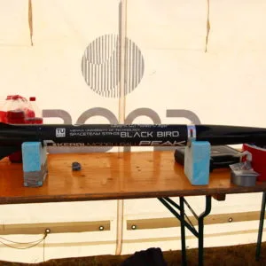
STR-03
- Code Name: Black Bird
- Release Date: 08/2013
- Diameter: 104 mm
- Length: 1650 mm
- Mass: 3700 g
- Stages: Single
- Propulsion: CTI K570
- Separation: Pneumatic
- Recovery: Single
- Electronics: FMS 2.1
- Flights: 1

STR-03 Black Bird
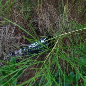
Learning the hard way
When our rocket STR-03 “Black Bird” left the ramp it was already doomed to go on a ballistic trajectory and hit the ground at about 150m/s (540km/h). back then we didn’t know, but 18 seconds later when recovery-ejection was triggered and the dedicated servo tried to open the ball-valve (to release pressure from a CO2-capsule into the parachute-compartment) it stuck. Telemetry showed that the motor was not able to turn the valve open. therefore no Co2 from the Capsule into the parachute-compartment, no pressure to separate the nosecone-section, no drogue, later on no parachute and BANG.
Last-Minute Change of Circuit-Board
How could that be? We tested the separation-valve several times and were pretty confident in our new ejection-mechanism. However during construction we detected an issue, that the ball-valve was a lot harder to open when it was under pressure(approx. 58 Bar) for more than an hour (somehow the valve-ball got pressed into the Teflon seat). We decided to use a servo with significantly more torque (120Ncm instead of 31Ncm) and after that the valve opened reliable any time.
Rather “last minute” we exchanged the servos original circuit-board against a board based on OpenServo V2 from Sparkfun (which had the advantage to feed back actual position and speed – something that ordinary servos cannot). We tested the ejection-mechanism after that and it worked fine, but we did not do the long-time-under-pressure test…
What we did not find out was, that the pimped servo for some reasons had less torque than with its original circuit-board; the degradation in torque was not noticeable at standard conditions, but it “ate” our margin to be able to open the valve after more than an hour under pressure. And the time from pre-launch-assembly to actual launch was more than that.
Landing site
We tried to estimate the crash-site-location from the received gps-points, but sadly the search area was quite large and a rough terrain. Search time was very limited too, as it was not allowed to be around during launches. After all, there is still hope that somebody might find our rocket or parts of it later on and identify it from one of the stickers…
Conclusion
It was a “hard lesson to be learned” and it is really bad to loose a vehicle at maiden flight. At the other hand about two thirds of our effort went into making the tools for STR-03. The next version – STR-03A – will be significantly improved and easier and faster built than its predecessor. Last but not least STR-03 in fact accomplished its mission: We received most of the desired data via telemetry. Analysis is still ongoing and results will be presented later on.
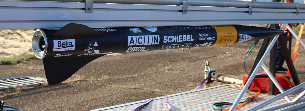
STR-03A
- Code Name: Phoenix
- Release Date: 08/2014
- Diameter: 104 mm
- Length: 1700 mm
- Mass: 3750 g
- Stages: Single
- Propulsion: i.a. CTI K570, AT I300T
- Separation: 2x Pneumatic
- Recovery: Dual
- Electronics: FMS 2.3
- Flights: 5

STR-03A Phoenix
Black Bird reloaded

The rocket STR-03A Phoenix is the next level of the STR-03 Black Bird, which was lost during its maiden voyage in the south of France as a result of complications in triggering the valve for the separation mechanism. Thankfully, due to the live telemetry data we received during its launch, we were able to analyse the rockets flight. This proved to be indispensable for the further development of the rocket, leading to the development of Phoenix.
Successful Maiden Voyage in Biscarosse at C’Space 2014
STR-03A Phoenix completed its first flight on the 27th August, 2014. It separated as planned after 18 seconds flight time at an altitude of 3 km and slowly returned to earth via parachute. As a result of the live telemetry data sent to the self-programmed ground station, the rocket was quickly located 4 km away from the launch point.
Further Developments on the Rocket Separation
Optically, STR-03A Phoenix is indistinguishable to STR-03 Black Bird. It is also built to use the same reload, CTI K570, with a maximum thrust of 893N (total impulse 2063 Ns). The FMS (Version 2.2) has been further improved and Phoenix has a newly developed pneumatic separating mechanism which has been redundantly designed to house two separating mechanisms. This way a reliable separation at the highest point of its flight path and the safe return of the rocket to earth can be guaranteed. Furthermore, even though the rocket houses two separating mechanisms, the mass of Phoenix remains identical to that of Black Bird.

STR-04
- Code Name: Strive
- Release Date: 08/2014
- Diameter: 104 mm
- Length: 2400 mm
- Mass: 5600 g
- Stages: Double
- Propulsion: CTI K570, AT I600 R
- Separation: 4x Pneumatic
- Recovery: Dual
- Electronics: 2x FMS 2.2
- Flights: 2

STR-04A
- Code Name: Strive
- Release Date: 05/2015
- Diameter: 104 mm
- Length: 1620 mm
- Mass: 3300 g (CTI J420) / 2800 g (AT I218R)
- Stages: Single
- Propulsion: AT I218R, CTI J420
- Separation: Pyrotechnic
- Recovery: Dual
- Electronics: 1x FMS 3.0
- Flights: 2

STR-Needle
- Code Name: Needle
- Release Date: 05/2015
- Diameter: 56 mm
- Length: 1230 mm
- Mass: ~ 1100 g
- Stages: Single
- Propulsion: i.a. CTI H87, AT I218 R, 3x Klima D9
- Separation: Pyrotechnic
- Recovery: Single
- Electronics: FMS. 3.0 – 3.2
- Flights: 6
STR-Needle
STR-Needle is our first rocket with major 3D printed components.
At an ominous length of near 1.2 meters, Needle is our smallest rocket of the STR (Space Team Rocket) series.
STR-05
- Code Name: Fury
- Release Date: 06/2015
- Diameter: 102 mm
- Length: 1590 mm
- Mass: 3775 g
- Stages: Single
- Propulsion: CTI K570
- Separation: 2x Pneumatic
- Recovery: Single
- Electronics: FMS 2.3
- Flights: 1

STR-05 Fury
The next instalment of the STR series is the STR-05 “Fury”. The sixth rocket in the series celebrated its maiden voyage in Manching, Germany, and reached an altitude of 500 meters with an AT I285R motor.
Design Phase and First Model
Following the success of STR-04 the previous year, which flew with a dummy motor in the upper stage, STR-05 was intended to be our first successful two staged rocket, which meant that a lot of new strategies had to be developed. The electronics mounter was split up into several modules, allowing for easy rearrangement of the modules within the rocket. An igniter was also designed, allowing for the ignition of the second motor once the rocket had reached an appropriate altitude and attitude.
Due to some last minute changes, Fury’s airframe material had to be changed from carbon fibre to reinforced PVC. With a 2.74 meter long, two staged, PVC rocket, the team made its way to the annual C’space competition.
C’Space 2015 (Tarbes, Frankreich)
At the competition itself it was apparent that the rockets PVC airframe was not capable of withstanding the bending tests of the competition. Due to time constraints and the anyway modular structure of the electronics mounter, the decision was made to fly Fury as a one staged rocket. Fury was rebuilt within 24 hours, however not all electronical problems were solved within this time frame. Thus, the decision was made to postpone Fury’s maiden voyage to a later date in order to not risk a ballistic flight.
Rocketry Day Manching
One month after the C’Space competition the Space Team attended the rocketry days in Manching, Germany, organized by the Arbeitsgemeinschaft Modellraketen and Solaris-RMB. With enough time to iron out the remaining software problems and a fresh coat of paint, Fury’s maiden voyage was celebrated on the 22nd of August and reached an altitude of 500 meters.
STR-06 “Watney”
- Code Name: Watney
- Release Date: 05/2016
- Diameter: 102 mm
- Length: 1620 mm
- Mass: 5700 g (max.)
- Stages: Single
- Propulsion: I300-AT, K570
- Separation: 2x Pyroless recovery
- Recovery: Dual
- Electronics: FMS 3.2
- Flights: 2

STR-06 Watney
Ever since the TU Wien Space Team was founded back in 2011, it has been an annual tradition to build a new experimental rocket for the French space agency CNES and Planète Sciences in order to launch at their annual launch campaigns. STR-06 is the new installment of our successful rocket series. Ever since 2015 the design, creation, and launch of the new rockets has been entrusted to new team members in order to bestow the existing knowledge to newcomers.
Aim
This years rocket, while still housing trusted components from previous rockets, has a few new additions, one of which is the new recovery system. The old pyrotechnic free release mechanism was completely redesigned based on the system developed by Troy Prideaux. The pressure chamber was filled with liquid CO2 instead of pressurized air however, which reduces the size of the recovery system. For a two staged recovery, the chute release is realized with the chute release by Jolly Logic.
Constructing the Airframe
After the construction of the airframe at Peak Technology back in February 2016, the out of PLA 3D printed fincans were attached to the frame and reinforced using fibreglass. The nosecone was also 3D printed out of PLA and reinforced with fibreglass.
Maiden Voyage and Roll-out
For the first time in TU Wien Space Team’s history, the new rocket for the CNES event was ready already by May. This meant that STR-06 experienced its successful maiden voyage in Leipzig, Germany and was already rolled out at our Space Event later that month.
Technological Requirement Evaluation in Paris
At the end of May, Sebastian Seisl and Andreas Bauernfeind travelled to Paris for the technological requirement evaluation for C’Space 2016. Here, STR-06’s ability to launch without problem was demonstrated using videos from the launch event just two weeks prior.
Finishing the Pyroless Recovery Mechanism
Despite passing the evaluation, project STR-06 wasn’t quite done yet. The new pyroless recovery mechanism had to be finished. After several weeks of hard work, dozens of tests, and several modifications three new systems were created just in time for the C’Space event. Two of the systems were installed in the rocket and the third acted as a backup in case one of the first two would be damaged during testing. Despite a few hiccups, the newly developed system proved to be reliable.
C’Space 2016
After a software update of the Flight Management System (FMS) and the construction of an improved electronics mount, there was seemingly nothing that could stand in the way of a successful launch in France. The final technological requirement evaluations at the event itself proved to be quite time consuming, however even these were passed after hard work.
Tuesday, the 26th July 2016 was the dreaded day. The team prepared the rocket for the launch and nervously checked the final checklist. The flight took place as planned and climbed to an altitude of 2830 meters. The new recovery system separated the rocket as planned and the drogue, and later the main parachute, brought the rocket back to earth at a controlled speed.
Manching 2016
After C’Space it was clear that the next goal was going to be- the first supersonic flight and the first two staged flight. While the supersonic flight was not possible due to regulatory reasons, the first two-staged flight was fulfilled in Manching, Germany and celebrated with more members of the Space Team on site.
Supersonic flight 2016
But shortly after that, we found a launch site where it was possible to start STR06 with supersonic velocity.
Summary
Thanks to the many launches with different technological requirements, the TU Wien Space Team was able to gain a lot of experience from STR-06. “Watney” is one of our most successful projects and is a great foundation for next projects, such as “The Hound”. This is largely thanks to the always reliable electronics of all Space Team rockets.
STR-06 “Watney Supersonic”
- Code Name: Watney Supersonic
- Release Date: 08/2016
- Diameter: 102 mm
- Length: 1620 mm
- Mass: 3776 g
- Stages: Single
- Propulsion: H148R, K1100-AT
- Separation: Pyrotechnic charge
- Recovery: Dual
- Electronics: FMS 3.2
- Flights: 2

STR-06 “Watney 2-staged”
- Code Name: Watney 2-staged
- Release Date: 08/2016
- Diameter: 102 mm
- Length: 2470 mm
- Mass: 6655 g
- Stages: 2
- Propulsion: I600-AT (booster), Klima D9 (sustainer)
- Separation: Pyrotechnic charge (booster), 2x Pyroless recovery (sustainer)
- Recovery: Single (booster), Double (sustainer)
- Electronics: FMS 3.2
- Flights: 1

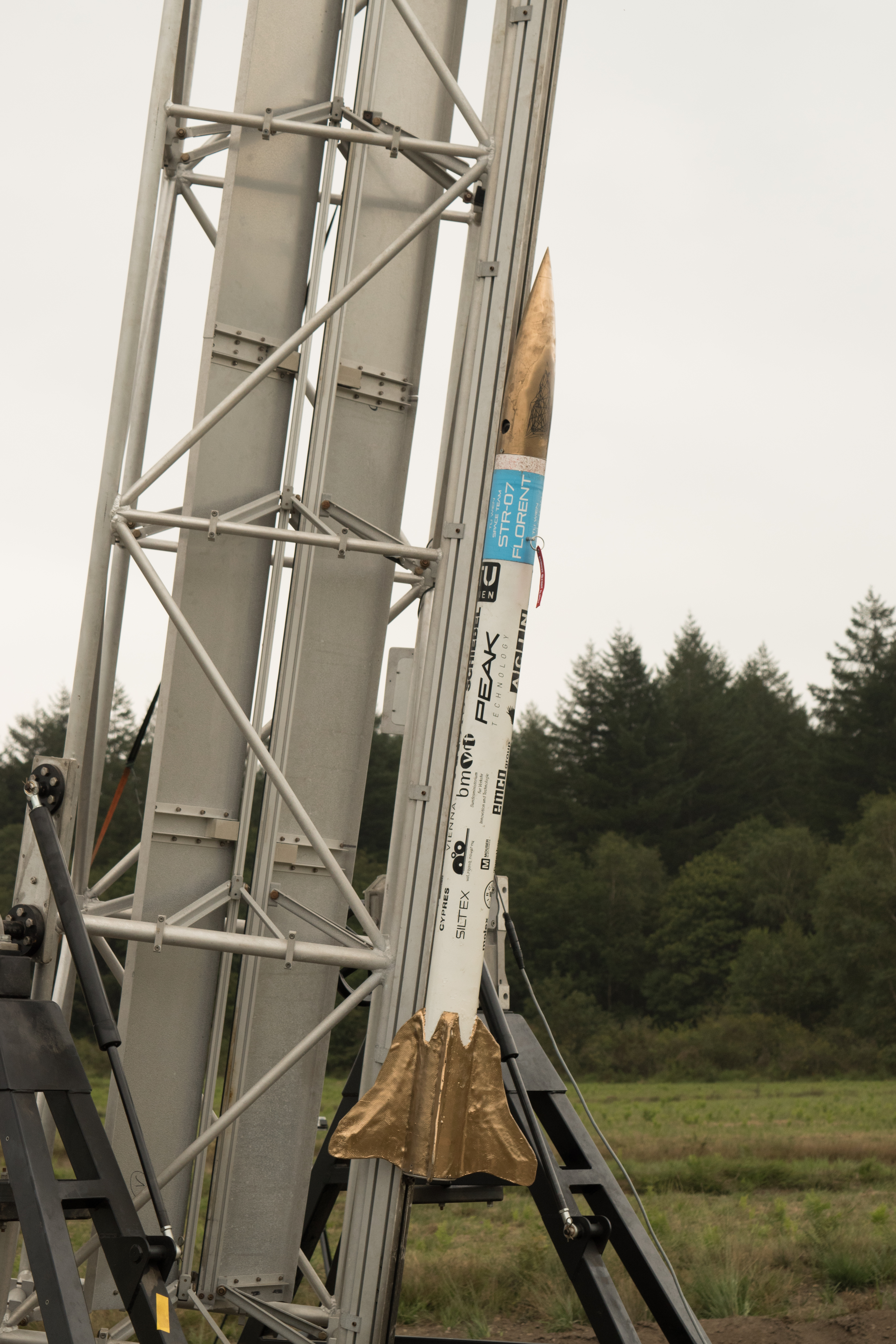
STR-07
- Code Name: Florent
- Release Date: 07/2017
- Diameter: 102 mm
- Length: 1940 mm
- Mass: 5636 g
- Stages: Single
- Propulsion: Pro75 L800-P
- Separation: 2x Pyroless recovery
- Recovery: Dual
- Electronics: FMS 3.2
- Flights: 1
STR-08
- Code Name: Coyote
- Release Date: 07/2018
- Diameter: 194 mm
- Length: 2440 mm
- Mass: 17790 g
- Stages: Single
- Propulsion: Pro75 L800-P
- Separation: Mechanic
- Recovery: Single
- Electronics: FMS 3.2
- Flights: 1
STR-09
- Code Name: Asimov
- Release Date: 07/2019
- Diameter: 151 mm
- Length: 2230 mm
- Mass: 6600 g
- Stages: Single
- Propulsion: Pro54 K570-7
- Separation: Mechanic
- Recovery: Single
- Electronics: FMS 3.4
- Flights: 1
STR-10
- Code Name: Leonor
- Release Date: 10/2020
- Diameter: 104 mm
- Length: 1800 mm
- Mass: 4100 g
- Stages: Single
- Propulsion: Pro54 K445-7
- Separation: Clampband
- Recovery: single refeed
- Electronics: FMS 3.4
- Flights: 1
FIRST 19/20
FIRST campaign 2019/2020
During the winter semester 2019 Project FIRST began its second installment and was able to build on the success of the previous year. With 18 Teams of two to four persons participating, the already high expectations were surpassed. In the beginning lots of workshops and seminars about rocket basics, simulations with OpenRocket, 3D CAD design, 3D printing, etc. were held to give the new members the necessary know-how for building and flying their first own rocket.
On December 13 and 17 the preliminary design review (PDR) took place where experienced Space Team members took a look at the initial design ideas, simulations and launch checklists that the teams came up with so far. All teams were well prepared and passed the PDR successfully. This allowed the teams to start constructing and building the first rocket parts. About two weeks before the end of the semester, from January 14 to 16, the final rocket designs were closely inspected by longstanding Space Team members during the critical design review (CDR). At this point in time all parts where already manufactured or at least available as 3D models. As expected, the teams performed well again.
The FIRST launch event in Straubing, Germany, was planned as a single day event which made it logistically impossible to allow all 16 remaining teams to start there. Therefore, two alternative launch possibilities in May and September were offered. Unfortunately, both of them had to be cancelled later on due to the COVID-19 pandemic. This means that thus far only the four teams which already participated in the first event on March 1 were able to launch their rockets. To the delight of everyone involved all rocket starts went well and apart from a few scratches and a broken fin, everything was recovered intact. So, at least for these four teams the project was completed successfully. Some of the other teams stayed positive and motivated even during the corona crisis and have already signed up for the next FIRST campaign to get another chance to experience their first rocket launch.
FIRST 18/19
FIRST campaign 2018/2019
After the recruiting event on November 14th 2018 the very first edition of project FIRST was started. It enjoyed a lot of popularity and eight teams with three to four participants each were present at the official beginning – the course on rocket basics. Subsequent seminars and workshops on OpenRocket, SolidWorks and 3D printing were well-attended too.
The preliminary design review (PDR) took place on December 19th. Design drafts for the mechanical structure as well as a simulation of the rocket were examined by three longtime Space Team members. Also a launch checklist had to be provided. The teams were well-prepared and completed the PDR successfully. A couple weeks later, the critical design review (CDR) was conducted. Here, the final design had to be presented. All components had to be available as 3D models or as actual hardware. The new members performed well again and had to make only minor adjustments.
The next challenge was to build the actual rocket. With the launch event approaching fast, a lot of cutting, drilling, 3D printing, gluing, screwing and wiring was done especially in the last week. Six of the originally eight teams managed to finish their rocket in time – a remarkable achievement!
The launch event took place in Straubing on March 2nd. Despite the bad weather – it was a cloudy, cold and windy day – five of the six teams successfully launched their rocket. For a more detailed report of the event see here. The sixth team as well as those who could not come to Straubing are still working diligently and plan to fly their rocket at the next possible event – most likely in Leipzig at the end of May.
With that project FIRST is not completed yet, but it can already be seen as a success. Therefore it will almost certainly be renewed in the winter semester of 2019.
Hier findet sich die Vorstellung der Projekts durch den Projektleiter Patrick Kappl im Zuge des Space Events 2019:
Penrose
Penrose was a medium-sized hybrid rocket project, that was active from spring 2022 to autumn 2023. The rocket was originally designed to fly to 3 km at EuRoC 2024. An engine prototype was developed and manufactured in-house for this purpose. Just like the Lamarr project, the rocket was designed for operation with liquid oxygen. (However, with a solid ASA grain instead of ethanol as fuel.) In addition, a complete airframe, including recovery system was also developed. The latter consisted of a folding belt mechanism, similar to the STR rockets.
One of the highlights of the project was definitely the first flight in August 2023 in Manching in Bavaria.
Especially at the beginning, the project was very much characterised by the construction of a new test stand, which was then increasingly taken over by Lamarr over time. In general, there were some overlaps, which ultimately led to the two projects being merged.
press coverage (German)
A small selection of press reports on the activities of the TU Wien Space Team.
2025
2024
2021
Wissensraum veröffentlicht einen zweiteiligen Artikel: Besuch beim TU Wien Space Team.
2020
30.Oktober 2020
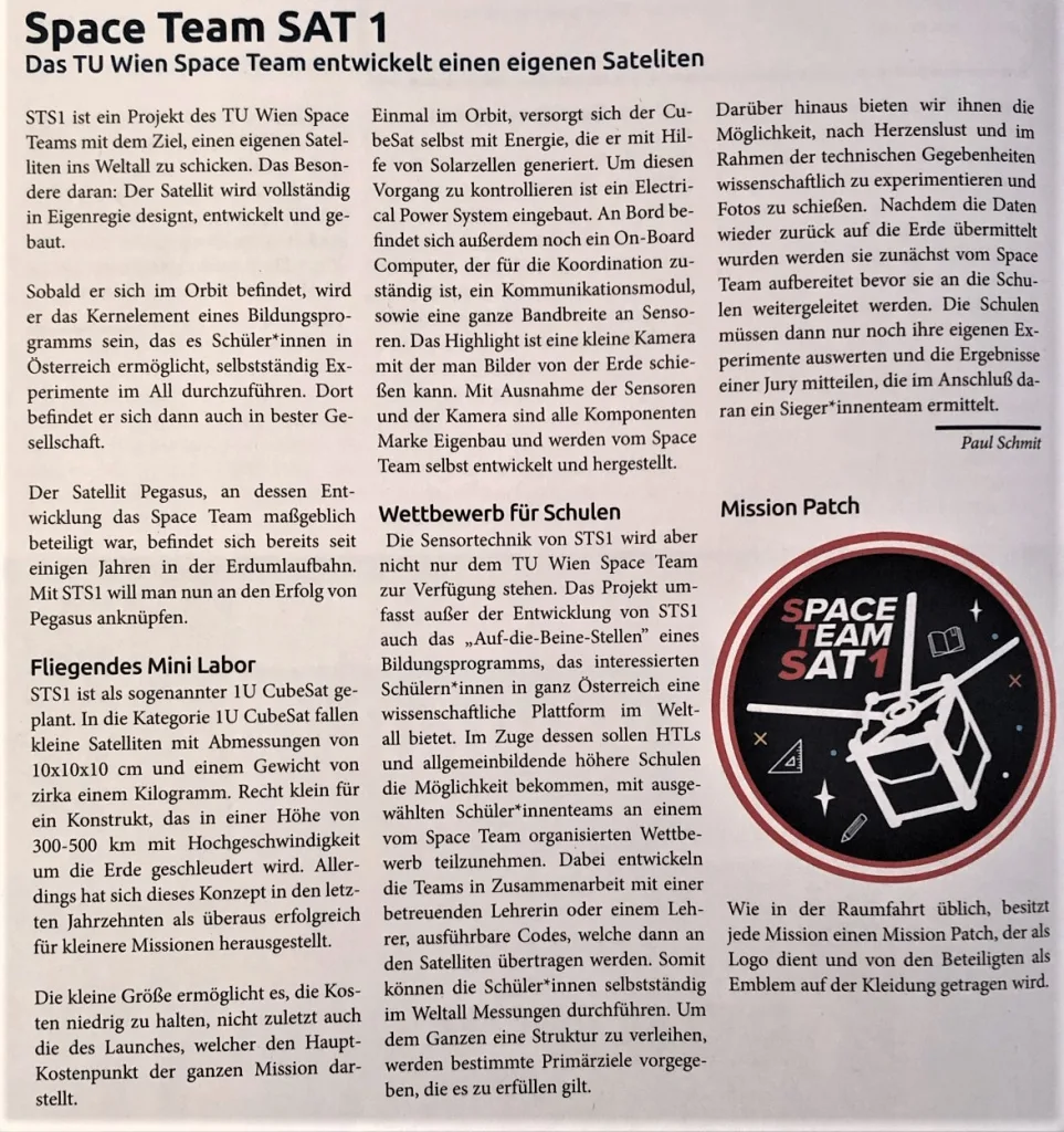
Die Zeitschrift htu.info veröffentlicht einen Bericht über unseren CubeSat STS1.
17.September 2020
Die Website der TU Wien berichtet von unseren Plänen für einen CubeSat.
2019
27.November 2019
Mach 5 Low-Down berichtet von studentischen Rekordversuchen, darunter auch uns.
12.November 2019
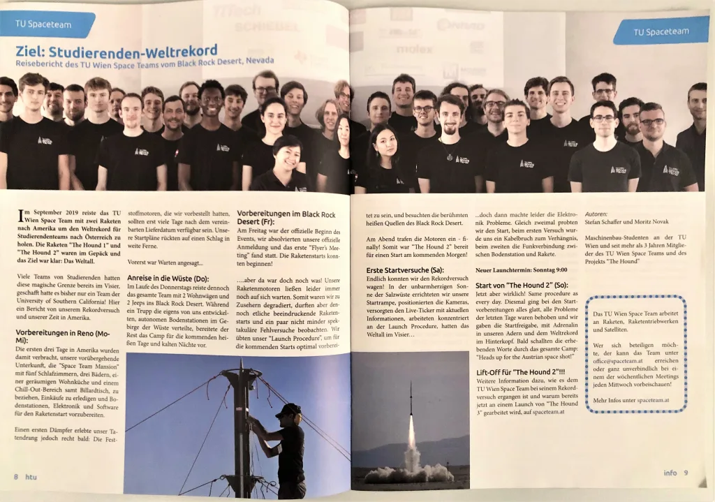
Die Studentenzeitung HTU Info veröffentlicht einen Reisebericht von unserem Rekordversuch in den USA.
31.Oktober 2019
Der Wissenschaftsblog Schrödingers Katze berichtet über das TU Wien Space Team.
19.Oktober 2019
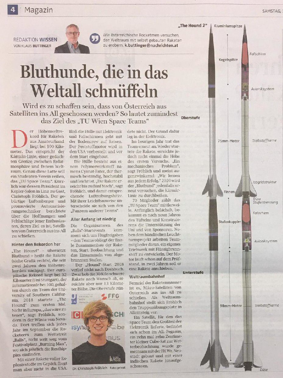
Die Oberösterreichischen Nachrichten berichten online und in Print über unseren Präsidenten Christoph Fröhlich und die Projekte des TU Wien Space Teams.
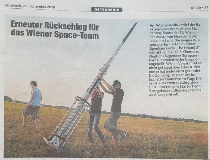
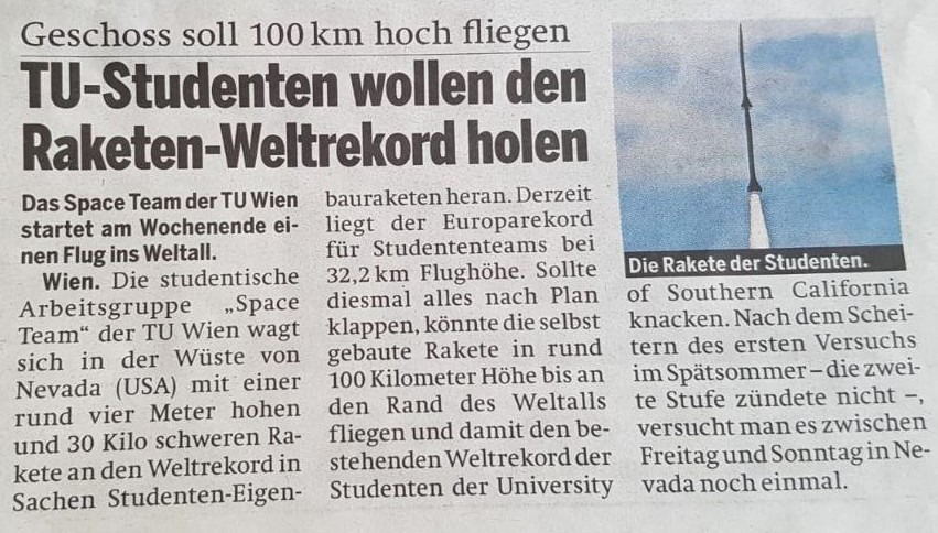
September 2019
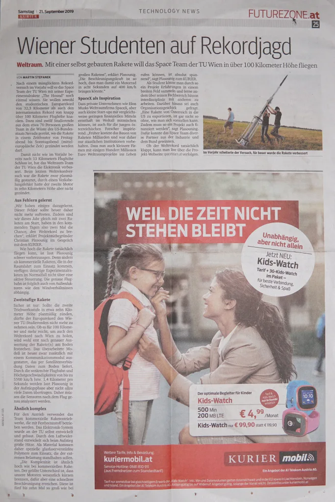
Unser Europarekordversuch mit der Rakete “The Hound” erregt national und international viel Aufmerksamkeit, unter anderem werden folgende Beiträge online veröffentlicht:
Website – TU Wien
Website – futurezone.at
Website – Der Standard
Website – Kleine Zeitung
Website – Vienna.at
Website – factorynet.at
Website – ORF.at (18.9.2019)
Website – ORF.at (23.9.2019)
Website – W24
Website – Mach5SlowDown
Website – Golem.de
In Print erscheinen diese Berichte:
Außerdem sind wir mit einem 10-minütigen Interview eines unserer Teammitglieder im Radio Oberösterreich zu hören.
21.Juli 2019
Die Kronenzeitung veröffentlich folgenden Beitrag über unser Projekt “The Hound:
20.Juli 2019
Auf dem Fernsehsender ORF1 wird ein Beitrag zum Jubiläum der Mondlandung gezeigt, der auch ein Bericht über das TU Wien Space Team beinhaltet.
8.Juli 2019
Der Kurier berichtet von der diesjährigen Kinderuni, vom TU Wien Space Team und unserem Vize-Präsidenten Moritz Novak.
28.-29.Juni 2019
Die Zeitung “Die Presse” berichtet sowohl online also auch in Print von unserem CubeSat-Projekt DISCO ONE.
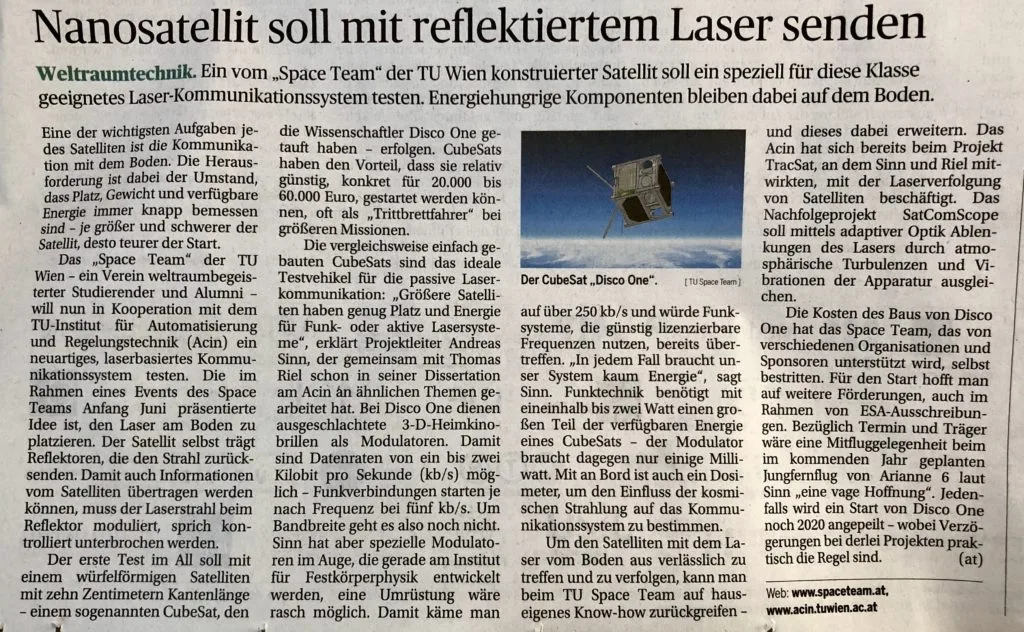
1.-2.Mai 2019
Auf der Website des Ars Electronica Centers in Linz und einer Presseaussendung wird über den erfolgreichen Verlauf des 2.österreichischen CanSat Bewerbs und die Beteiligung des TU Wien Space Teams berichtet.
25.April 2019
Auf der Website von Riot Games und Summoners-Inn wird von unserem Projekt “Daedalus” erzählt.
27.März 2019
Die bmvit Infothek berichtet von unserem Projekt “Daedalus”.
16.März 2019
Die österreichische Tageszeitung “Die Presse” druckt einen Bericht über das Projekt “Daedalus”.
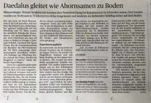
13-14.März 2019
Auf den folgenden Seiten wird von unserem gelungenen Projekt “Daedalus” berichtet.
Website – Der Standard
Website – Krone
Website – Futurezone.at
Website – ORF.at
Website – Kleine Zeitung
Website – Tiroler Tageszeitung
Website – Innovationorigins.com
Website – Raumfahrer.net
Website – Economy
Website – ESA
Twitter – ESA
27.Februar 2019
In der Kronenzeitung im Abschnitt “Villach” wird über Christian Plasounig, den Projektleiter von “The Hound” berichtet.
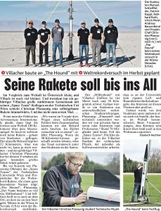
12.Februar 2019
Im Radio NJOY 91.3 Wissenschaftsradio ist ein 30-minütiges Interview mit unserem Vize-Präsidenten Tobias Bauernfeind zu hören.
9.Februar 2019
In Radio Wien wird über unser Team berichtet.
In der Tageszeitung Heute wird ein Zeitungsartikel veröffentlicht.
8.Februar 2019
In der Fernsehsendung “Servus am Abend” auf ServusTV wird ein Kurzbericht über unser Team gezeigt.
7.Februar 2019
Auf ORF.at wird außerdem ein Bericht veröffentlicht.
2018
19.Dezember 2018
Computerwelt.at berichtet vom ersten Lego League Event in Wien und der Beteiligung des TU Wien Space Teams.
20.November 2018
In den Oberösterreichischen Nachrichten wird über unser Vorstandsmitglied Ulrich Meisl und das TU Wien Space Team berichtet.
22.Oktober 2018
Es wird auf der Website Mach5Low-Down über unseren Rekordversuch der Rakete The Hound berichtet.
Außerdem wird im fti Blog von unserer Teilnahme an der European Researchers’ Night erzählt.
17.September – 3.Oktober 2018
Auf folgenden Kanälen wird über unseren Weltrekordversuch im Rahmen des Projekts The Hound berichtet:
Website – TU Wien
Website – “Krone”
Website – ORF.at (21.09.2018)
Website – ORF.at (24.09.2018)
Website – APA Science (18.09.2018)
Website – APA Science (25.09.2018)
Website – futurezone.at (18.09.2018)
Website – futurezone.at (21.09.2018)
Website – futurezone.at (24.09.2018)
Website – “Salzburg 24”
Website – “Kleine Zeitung” (18.09.2018)
Website – “Kleine Zeitung” (24.09.2018)
Website – “Der Standard” (18.09.2018)
Website – “Der Standard” (24.09.2018)
Website – “Salzburger Nachrichten”
Website – trendsderzukunft.de
Website – Infothek des Bundesministeriums für Verkehr, Innovation und Technologie (21.09.2018)
Website – Infothek des Bundesministeriums für Verkehr, Innovation und Technologie (26.09.2018)
Website – “Vorarlberger Nachrichten” (18.09.2018)
Website – “Vorarlberger Nachrichten” (25.09.2018)
Website – Magazin Economy
Website – “Oberösterreichische Nachrichten”
Website – vienna.at
Print – “Vorarlberger Nachrichten”
Print – “Krone”
Print – “Kurier” (21.09.2018)
Print – “Wiener Bezirkszeitung”
Außerdem werden folgende Videobeiträge veröffentlicht:
Website – W24 (18.09.2018)
Website & TV – W24 (20.09.2018)
TV – Servus TV in der Sendung “Servus am Abend”
Twitter – RUAG Space
17.Mai 2018
Auf futurezone.at wird über das TU Wien Space Team berichtet.
9.May 2018
Die Website der TU Wien berichtet über unser bevorstehendes “Space Event 2018”.
13.April 2018
Das Magazin frei.haus erzählt von unserer Beteiligung an der “Langen Nacht der Forschung”.
Außerdem wird auf frei.haus über das Projekt “Daedalus” berichtet.
12.April 2018
Auf der Website futurezone.at von unserer Kooperation mit den PTScientists erzählt.
11.April 2018
In einer Presseaussendung der APA wird von unserer Beteiligung am 1.Österreichen CanSat Wettbewerb berichtet.
März 2018
In folgenden Medien wird über den bevorstehenden Start der “Space Seeds” im Rahmen von REXUS: Projekt Daedalus berichtet:
Website – ORF.at
Website – “DerStandard”
Website – Studium.at
Website – APA Science
Website – “Hamburger Abendblatt”
Magazin – trend 9.3.2018
14.Jänner 2018
Auf ORF.at wird über die beginnenden Experimente an Board des Cubesats “Pegasus” berichtet.
9.Jänner 2018
Auf der Nachrichtenseite “WN24” wird über den Cubesat “Pegasus” berichtet.
2017
30.September 2017
In den “Salzburger Nachrichten” erscheint eine Berichterstattung über (österreichische) Satelliten und den Cubesat “Pegasus”.
31.August 2017
In der “DFZ – Die Floridsdorfer Zeitung” erscheint ein Artikel über das Cubesat-Projekt “Pegasus”.
20.Juli 2017
In der Infothek des “Bundesministeriums für Verkehr, Innovation und Technologie” erscheint ein Artikel über das Cubesat-Projekt “Pegasus”.
23.Juni 2017
futurezone.at berichtet über den erfolgreichen Start des Cubesats “Pegasus”.
Die Zeitung “Der Standard” erstattet Bericht über den erfolgreichen Start des Cubesats “Pegasus”.
21.Juni 2017
Das Wissenschaftsmagazin HEUREKA aus dem Falter Verlag berichtet über unsere Tätigkeiten und unser Mondlandemodul.

22.Mai 2017
Die Zeitung “Der Standard” berichtet über den bevorstehenden Start des Cubesats “Pegasus”.
12.Mai 2017
Das Fachmagazin “Factory” publiziert einen Artikel über den Nanosatelliten “Pegasus”.
10.Mai 2017
Auf der Website der TU Wien wird über das Cubesat-Projekt “Pegasus” berichtet.
Im Standard erscheint ein Artikel über den österreichischen Nano-Satelliten “Pegasus”.
Im Fachmagazin “monitor” wird über das Cubesat-Projekt “Pegasus” berichtet.
Die “Kronen Zeitung” berichtet über den baldigen Start des Cubesats “Pegasus”.
10.März 2017
Auf der Website der TU Wien wird über das Projekt Daedalus berichtet.
2016
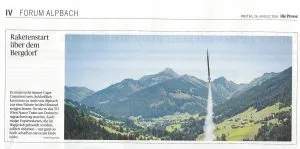

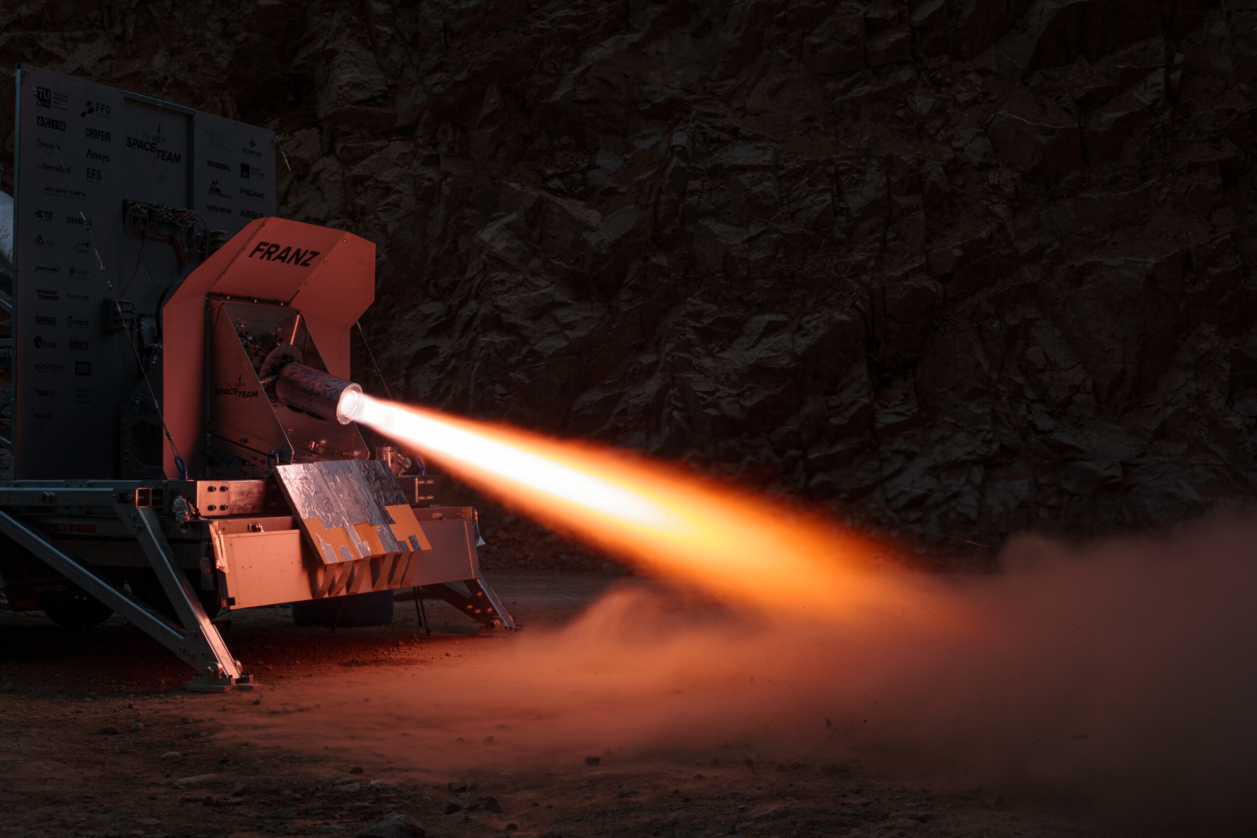
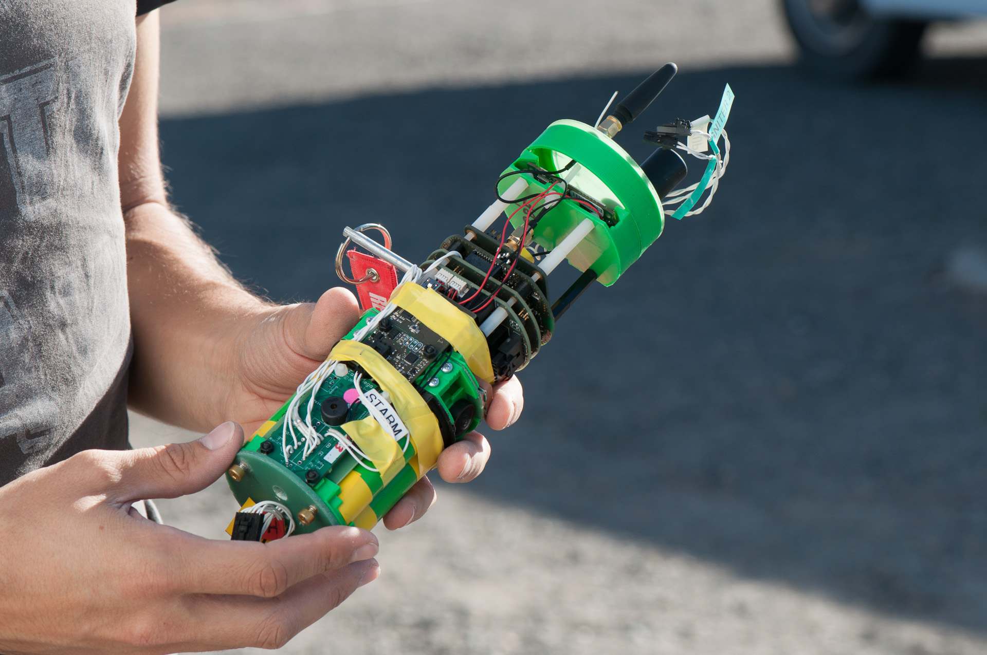
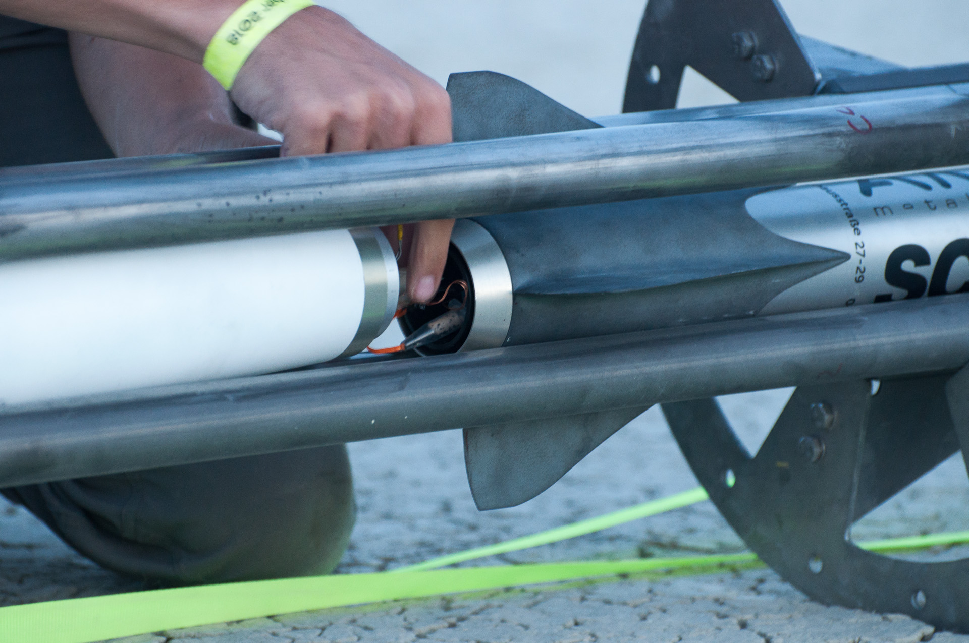
2015
11.September 2015
In der Tageszeitung derStandard erscheint ein Artikel über unser Lunar-Landing-Module:

10.September 2015
Im Wien-Magazin auf W24 werden unser Mondlandemodul und unsere Raketen im Rahmen des Wiener Forschungsfestes voregstellt (2.Beitrag)
24. Jänner 2015
Die Presse – “Weltraummission im Kleinformat” von Andreas Tanzer
2014
8. August 2014
In einem Beitrag der Reihe Dimensionen zu den Testversuchen der Mondrover von Parttime-Scientists am steirischen Erzberg wird auch das TU Spaceteam erwähnt. Beim ORF gibt es eine Übersicht.
3. Mai 2014
Die Tageszeitung «Die Presse» berichtet in ihrer Printausgabe sowie online vom Space Day, der am 26. Mai an der TU Wien stattfand. Unter Beteiligung der Europäischen Weltraumorganisation ESA wurden die aktuellen Projekte und Kooperationen des TU-Space-Teams präsentiert.
2013
10. September 2013
Die Tageszeitung «Der Standard» berichtetet unter dem Titel «Per Blechdose durch die Galaxis» vom Space Day im Technischen Museum Wien. Erwähnt wird dabei neben dem Projekt CanSat auch das TU Space Team.
21. August 2013
In seiner Printausgabe bringt der «Falter» eine Reportage über das TU Space Team. Redakteurin Ruth Eisenreich berichtet dabei über aktuelle Projekte des Space Teams, stellt einige Mitglieder mit ihrer Motivation vor und gibt einen Ausblick auf kommende Wettbewerbe.
2012
keine Publikationen bekannt
2011
November 2011
Unter dem Titel «Auf Kuschelkurs mit der Rakete nach Frankreich» berichtet die Tageszeitung «Der Standard» in ihrem Print-Sonderteil «UniStandard» über das erste Raketenprojekt des TU Space Teams und die Vorbereitungen zum Start in Südfrankreich.
April 2011
Die Mitarbeiterzeitung der TU Wien «TU frei|haus» berichtet unter dem Titel «To boldly go where no student has gone before» über die Aktivitäten des Space Teams wie den Raketenbewerben in Frankreich und dem CanSat-Projekt.